Better Downward Camea

mrandt
Posts: 407
Joined: Mon Apr 27, 2015 10:56 am
Location: Stuttgart, Germany

Re: Better Downward Camea

Post by mrandt »

Hello,

it is really interesting to see all these camera mods. I thought I'd join the discussion and share what I have built.

I am using modified webcams and custom lighting for both up and downward vision. Basically, I stripped the PCB and optics from some webcams I had bought and put these into 3D printed enclosures I have designed for the purpose.

I believe the uplooking camera is just as important as the downlooking one - it is used to calibrate and compensate for needle wobble, which directly affects placment accurary of components when changing orientation (i.e. turn parts). It will be even more critical for aligning fine pitched chips or even BGA (never say never...).

I experimented with a few different cameras until I found a setup that works for me.

I chose a cheap logitech C270 for uplooking cam:
http://www.logitech.com/de-de/product/hd-webcam-c270

It has a CMOS camera sensor which has a physical resolution of 1280x720 pixels. The chip and USB communication support a decent framerate of about 25-30 fps. I found the sensor to be quite sensitive but still generate only little noise. The lense is fix focus at an unknown focal length. I would guess it must be somewhere between 2.5 and 3.5mm. Anyways, viewing distance and angle worked OK for me. Once you cut away a little glue, you can adjust the focus by turning the outer ring. The same CMOS sensor is apparently also used in more expensive Logitech cameras, often paired with a motorized focus adjuster - I think that is not helpful so no point in spending more money.
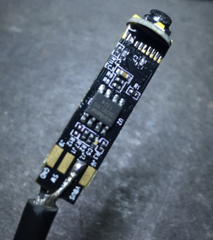
Uplooking camera optics, chip and PCB in custom case.
up_cam_01.jpg (19.37 KiB) Viewed 14860 times
Uplooking camera case closed.
up_cam_02.jpg (24.28 KiB) Viewed 14860 times
Uplooking camera with LED array mounted to table.
up_cam_03.jpg (22.47 KiB) Viewed 14860 times
For the downlooking cam, I went for a different model which I could mount vertically. I went for a cheap HD webcam by Ednet:
http://ednet-europe.eu/en/sortimente/us ... ld-004-56/

The CMOS in it supports "Full HD", meaning physical resolution of 1920x1080. However, the framerate drops to 10-15 at this resolution. For my purposes, 720p (1280x720) is more than sufficient and at that resolution (if set in driver), 25 fps are no problem. Again, the sensor does not produce much noise. Biggest advantage (and the reason I selected this cam) is that there is a standard M12 mount for the lense already, so I can easily fit a better lense as the original ones in webcams tend to have quite some distortion at the edges of the picture.

At the moment, I fitted a cheap lense with 2.8mm focal length, which distorts the picture quite a bit but less than original lense. I might swap this for a distortion free lense with similar focal length - should cost about 50 EUR, more than the camera... Another option I looked at is the Microsoft Life Cam - which has better frame rate and higher sensitivity but requires more work to fit standard lenses. I found a lot of discussions about modifying this cam in astronomy / star gazing forums and might give it a try if I find the time.

Again, I modeled and 3D printed a custom case for the camera and also included additional LED lighting.
Guts of Ednet camera.
down_cam_01.jpg (15.19 KiB) Viewed 14860 times
Downlooking camera in custom case.
down_cam_02.jpg (21.91 KiB) Viewed 14860 times
Downlooking camera in action.
down_cam_03.jpg (18.87 KiB) Viewed 14860 times
I hope this is helpful information if anyone wants to make their own cameras.

I plan to also post some pictures to illustrate image quality soon.

Best regards
Malte
RinusDamen
Posts: 32
Joined: Sun Apr 05, 2015 5:51 pm

Re: Better Downward Camea

Post by RinusDamen »

hello mrandt,

thanks for sharing your camera solution with our builders on the forum!
My pen camera seems to have a 8 mm diameter and so doesn't fit in the SK12 mount, although the picture looks more clear and sharp than the original (the original seems to be somewhat out of focus to me). So for now I keep the original camera to start with.
But for the up looking camera I like your solution a lot, where did you get these LED pcb's ? and is red light better than white? Would the hex shape you made perform better than the original white ring led's? how critical is the camera mount and alignment to the needle?

By adding an extra 20x40mm extrusion frame under the complete frame I'll create a 40mm space under the 'table', I will use 20x20 extrusion profiles to create the table, this way I can easily adapt the table for anything in the future.... I ordered the extrusion profiles today, once I got it mounted I will share some pictures on this forum.

By the way on one of your pictures I saw your needle construction, did you change anything to that also?
mrandt
Posts: 407
Joined: Mon Apr 27, 2015 10:56 am
Location: Stuttgart, Germany

Re: Better Downward Camea

Post by mrandt »

Hi Rinus,

focus is often an issue, as most "webcams" and "pencams" are focussed for a fixed viewing distance that is farther away than just a few millimeters. Once you rip the PCB, CMOS and optics from their casing, you can often adjust the focus.

With the endoscope cameras from the kit however, I think the problem is the CMOS chip in the first place. But hey, they work fine. I just wanted to take my vision system to a higher level. That is the beauty about open source hardware such as LitePlacer, if you ask my opinion :-)

I have made those LED pcb myself, etched at home actually because I did not want to wait couple days for my PCB fabber to make them... Nothing special about those boards.

The cam I use is very sensitive to red light. Also, I still had a bunch of red SMD LED. I think white would still work.

EDIT: Red seems to have been a good choice as I can easily add colour filters to almost eliminate the effect of ambient light... :-)

I am not sure if hex is better than ring, but this was the easiest for me to fabricate.

EDIT: Turns out, my LED array alignment for upward camera seems to have one big advantage over a basic ring light. As the light shines on the component at an angle of about 30° tilted to camera lense plane, there are no visible reflection / flares in the image!
On my downward cam, the LEDs are not tilted but mounted parallel to the lense and I sometimes see reflections. Thus, I will either need to add a diffusor or change the aligment, too.

So far, the results are still great: Needle wobble calibration and component alignment work like a charm. Also, my camera does not use much space underneath the table - just about 15mm.

How you mount the camera does not really make a difference for the accuracy - aligment however does. It just needs to be straight up and in a fixed position.

With regards to the needle, I have changed a lot. Not only to the needle but the whole pickup head. I will probably make another post about the changes I introduced on my machine.

Best regards
Malte
Last edited by mrandt on Mon May 11, 2015 2:08 pm, edited 2 times in total.
thereza
Posts: 138
Joined: Fri Feb 13, 2015 11:49 pm

Re: Better Downward Camea

Post by thereza »

I cut open the case of the included to see if it had a small enough profile, but it's still fairly long, in case anyone else is interested.

Image
Image
mrandt
Posts: 407
Joined: Mon Apr 27, 2015 10:56 am
Location: Stuttgart, Germany

Re: Better Downward Camea

Post by mrandt »

As promised, I have attached a few pictures to illustrate image quality of my LitePlacer's enhanced vision system.

The chip shown in the image is in a TQFP 44 package with 0.8mm / 31 mil pitch, the PCB has corresponding pads.

The images are screencaptures from LitePlacer UI in original resolution. I am not including the images inline, as they would appear with nasty scrollbars.

As the physical resolution of the cameras is more than the 640x480 displayed (1080p for downward, 720p for upward camera), the software currently only sees a smaller viewport of the total image.

I hope that Juha - and / or some volunteer contributers, including myself :-P - will enhance the software to have better control on zoom and viewport settings in the future, please see related discussion on GitHub issue #11:
https://github.com/jkuusama/LitePlacer/issues/11

Any questions, let me know.

Malte
Attachments
Upward cam looking at the chip (needle down) with red LED lighting on and zoom factor 2x enabled (no further filtering enabled)
uplooking_lighs_on_zoom2x.jpg (88.51 KiB) Viewed 14827 times
Upward cam looking at the chip (needle down) with red LED lighting on (no further filtering enabled)
uplooking_lights_on.jpg (87.19 KiB) Viewed 14827 times
Upward cam looking at the chip (needle down) with just ambient light
uplooking_lights_off.jpg (75.66 KiB) Viewed 14827 times
Downward cam looking at the matching footprint / pads on PCB
downlooking_pcb.jpg (144.6 KiB) Viewed 14827 times
Downward cam looking at the chip in tray before pickup
downlooking_part.jpg (101.99 KiB) Viewed 14827 times
JuKu
Site Admin
Posts: 1110
Joined: Thu Feb 14, 2013 3:06 pm
Location: Tampere, Finland
Contact:

Re: Better Downward Camea

Post by JuKu »

Much better than the standard cameras. I should look into offering something like this.
RinusDamen
Posts: 32
Joined: Sun Apr 05, 2015 5:51 pm

Re: Better Downward Camea

Post by RinusDamen »

hello mrandt,

Thanks for your Logitech C270 tip, I bought one (only E25,-), took it apart it's the perfect form factor for the liteplacer.
It's flat and easy to mount, I took off the small dot of glue on the focus ring and adjusted it for use with the liteplacer, splendid!
I'm planning to use a piece of RGB led strip as a red colored light source, I still have to mount that someway...

I noticed when looking (with the camera) into the needle mount that it looks somewhat off, when I move the gantry a bit to the left (still in the marked red box) it's (vertically) perfectly aligned with the camera, however in that case it is not exactly in the middle of the red box, could this become a issue later on? it looks like the needle is vertically off compared to the camera, when I tilt the camera mount it looks better, but I can see it's several degrees off. Maybe it's misalignment of the lens mount onto the Logitech PCB?!
I hope I explained my issue otherwise I have to post a screendump...

Do you also see this misalignment? maybe it's no issue at all, but since I'm building right now I would like to fix this if it's needed.
mrandt
Posts: 407
Joined: Mon Apr 27, 2015 10:56 am
Location: Stuttgart, Germany

Re: Better Downward Camea

Post by mrandt »

Hi Rinus,

glad you like the C270 logitech cam :-)

Regarding the observations you described:
I noticed when looking (with the camera) into the needle mount that it looks somewhat off, when I move the gantry a bit to the left (still in the marked red box) it's (vertically) perfectly aligned with the camera, however in that case it is not exactly in the middle of the red box, could this become a issue later on?
This is a common effect with standard lenses called "perspective error". It is caused by the fact that object farther away are projected smaller than those closer to the lense. Paired with the inherent distortion of a normal lense, vertically straight objects seem to tilt once they are moved away from the center of the camera.

Naturally, this happens on my machine as well:
Perspective error - needle off center to the right
off_center_right.jpg (30.07 KiB) Viewed 14772 times
Perspective error - needle off center to the left
off_center_left.jpg (31.81 KiB) Viewed 14772 times
Needle centered
Needle centered
centered.jpg (38.36 KiB) Viewed 14772 times
This could be cured by using a telecentric lense. I think, this illustration (by a manufacturer of lenses) explains it well:
http://vst.co.jp/en/products/images/fig_tc1.jpg

If you are interested in the physics, check out the following website which gives a detailed explantion:
http://www.opto-engineering.com/resourc ... s-tutorial

IMHO this is not necessary for the uplooking camera, because all objects of interest are at a known distance from the camera - which is PCB surface level. When you click "needle down", the needle will move to this level. So the problem is more or less narrowed down to a two-dimensional plane for both needle wobble calibration and component orientation.

I have adjusted viewing distance and focus so that objects on PCB surface level are projected as sharp and as undistorted as possible. The optimal distance seems to be about 32mm from lense to object (PCB level), which in my case means the lense is mounted about 30.5mm below the table surface.

This results in pretty straight lines when looking at a millimeter grid:
Grid (mm) on PCB surface level / 2D plane
grid.jpg (56 KiB) Viewed 14772 times
So far, I have not encountered any problems with the upward camera setup - while the perspective error on my downward camera is giving me some headaches... See related post here:
http://liteplacer.com/phpBB/viewtopic.p ... rt=20#p350

Cheers
Malte
thereza
Posts: 138
Joined: Fri Feb 13, 2015 11:49 pm

Re: Better Downward Camea

Post by thereza »

I think there is a simple solution to your downcamera perspective issue. Simply support multiple calibrations at different heights. The needle probing can measure the height of the surface being probed, and all you need is a dot at any height to determine the scaling at that height. It wouldn't take much more effort to interpolate the scaling to arbitrary heights. Let me know if there is a desire for this and I can code it. The actual code is simple, but it will require a revamp of how the scaling is applied across a ton of code. Then again, I've been doing some serious hacking away at the code already trying to simplify it and increase code reuse as much as possible (i.e. consolidating functions) and trying to migrate a lot of the code into supporting the PartLocation class which cleans up the code a lot (lets you do vector based math rather than copying X and Y values all over the place). For example, for the part location detection of aribrary angled tape, it's something like (PL are PlartLocation classes)

componentLocationPL = BaseHolePL + (part_number*partPitchPL + partHoleOffsetPL).Rotate( tapeSlopePL.ToRadians());
RinusDamen
Posts: 32
Joined: Sun Apr 05, 2015 5:51 pm

Re: Better Downward Camea

Post by RinusDamen »

My needle viewed in the middle doesn't give the same result as shown in your picture.
It's more somewhat like the picture were you show the needle to the right.
I can get the needle picture aligned centered, however in that case the needle is not in the middle of the view.
I'll have to try and rotate the camera 180 degrees to see if it's the camera's lens itself.
Post Reply