Hi all, this is my first post here, my LitePlacer kit is arriving tomorrow morning and I am frantically trying to get ready for it. I'm all ready to go except for one thing, where do I put the hole for the up facing camera?
I have scoured the directions and forums and have not found any answer other than "it has to be somewhere the machine can put the needle". I was hoping to have the hole cut before building the machine, it seems a lot easier to do it first rather than wait until the whole machine is built.
I've found measurements of the outside of the frame, so I can come up with where I want to put the frame on my table, but that doesn't help with where the needle can be relative to the frame.
I would appreciate if someone could let me know where this infamous area is relative to the frame. Say we make the lower left corner on the outside of the frame the origin (0,0), what are the coordinates of the region where the placer can put the needle? (please let me know the units, I'm in the US and prefer inches, but I know many of you like to use cm or mm)
A secondary question, how big to make the hole? I see some people with a fairly small hole and some with a fairly large hole, are there particular reasons for the hole size?
Thanks,
John S.
Location of up-camera hole
Re: Location of up-camera hole
Hello John,
the best location is somewhere along the movement path between part pickup (feeder) and the part placement location on the PCB. Many still place the hole near the lower left zero home location.
I decided to place the hole above the PCB area, which is not optimal if you don't use tape stripes of feeder in higher Y locations. The overhead of moving left of the PCB and then back to the placement location is in total faster than the long run movements to my current camera location.
If you follows Juhas approach using cut tape stripes on the table surface or using Maltes 3D printed tape holders you will probably fill 2/3 of the whole right area and part of the area above (in Y direction) the PCB location.
If you decide to use some type of tape feeders you will have an different usage of the area the nozzle can reach (this is btw. 580 x 370 mm).
I would suggest you don't drill the hole before you have finally assembled the machine and decided where to screw onto onto your table and how you intend to handle part pickup.
best regards
Manfred
Manfred
Re: Location of up-camera hole
The hole location is not very critical. The area on the left side where the needle can reach but the down camera can not is good, as the area is otherwise not used. There is no need for the cameras to see each other. Currently, the up camera is only used for needle wobble calibration; the hole doesn't need to be very big. In the future, we might get to use it for IC placement help. so it makes sense to make the hole somewhat bigger than needed. Mine is on the big side, at the time I made it I had no idea about how big it needs to be.
Here is what I have:
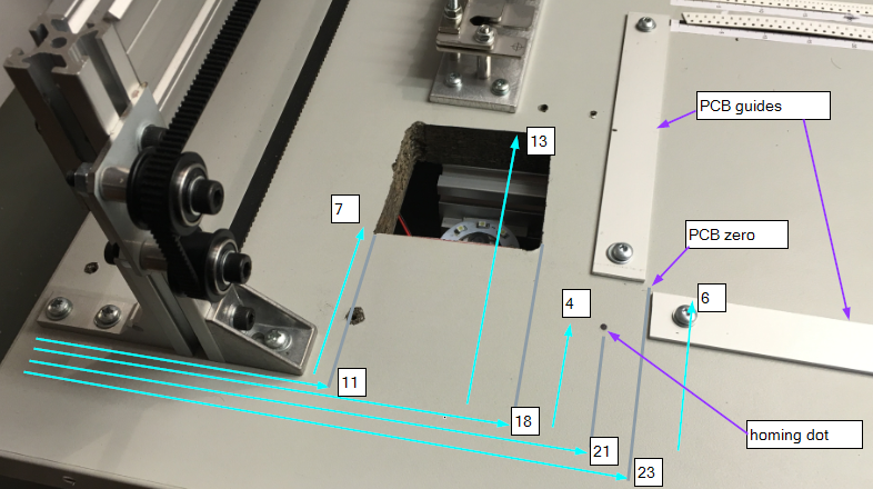
Ignore the unmarked holes, those are left over form earlier experiments. You can see the corner post structure, the up camera in its hole, the homing mark and the PCB jig. All measures are approximate, in cm.
Here is what I have:
Ignore the unmarked holes, those are left over form earlier experiments. You can see the corner post structure, the up camera in its hole, the homing mark and the PCB jig. All measures are approximate, in cm.
Re: Location of up-camera hole
Hi, i'm a newbie here. I've understood that this up-looking camera is more precise than the down-looking one, is it true ?mawa wrote: the best location is somewhere along the movement path between part pickup (feeder) and the part placement location on the PCB. Many still place the hole near the lower left zero home location.
I've seen few videos of different liteplacers, and some are only using the up-looking camera in its hole for placing each component,
but everyone (except one) have decided to place this up-looking camera in the left-down side.
So as you said, why not having this up-looking camera for example in the center of the table, between feeding zone and the PCB zone, In the case of using only this up-looking camera, in order to gain some significant processing time ?
My other question is the Z position of this up-looking camera : is it possible to place the camera not down in this hole but aligned with the table ?
Thanks, and congrats for this project and this forum, it's seems to be an alibaba cavern !
Re: Location of up-camera hole
> I've understood that this up-looking camera is more precise than the down-looking one, is it true ?
Not really, both cameras have the same resolution. I'm writing a software to use the up looking camera for placement, and it probably gives better results, as this function will correct parts that were misaligned in their pockets*, and also, have fewer user calibration points (a source of error) in the calculations.
*: But you can also use vision to locate the actual parts in the tape pockets, not just look for the tape holes or tape pockets.
> some are only using the up-looking camera in its hole for placing each component,
Those are using OpenPnP, another software for the machine. OpenPnP has this fuction, LitePlacer software doesn't yet.
> but everyone (except one) have decided to place this up-looking camera in the left-down side.
Because I have adviced so. Also, the left side of the table is not fully used, as the downlooking camera doesn't reach there.
> So as you said, why not having this up-looking camera for example in the center of the table, between feeding zone and the PCB zone, In the case of using only this up-looking camera, in order to gain some significant processing time ?
No particular reason, you can do that.
> My other question is the Z position of this up-looking camera : is it possible to place the camera not down in this hole but aligned with the table ?
Not really. Z -wise, the system assumes every thing happens on the PCB surface level. There is no correction or calibration for the nozzle at different Z levels. So, you either place the camera down from the table top, or raise everything up from the table. latter is far easier, even though you need to use a hole saw during hte assembly.
Not really, both cameras have the same resolution. I'm writing a software to use the up looking camera for placement, and it probably gives better results, as this function will correct parts that were misaligned in their pockets*, and also, have fewer user calibration points (a source of error) in the calculations.
*: But you can also use vision to locate the actual parts in the tape pockets, not just look for the tape holes or tape pockets.
> some are only using the up-looking camera in its hole for placing each component,
Those are using OpenPnP, another software for the machine. OpenPnP has this fuction, LitePlacer software doesn't yet.
> but everyone (except one) have decided to place this up-looking camera in the left-down side.
Because I have adviced so.
> So as you said, why not having this up-looking camera for example in the center of the table, between feeding zone and the PCB zone, In the case of using only this up-looking camera, in order to gain some significant processing time ?
No particular reason, you can do that.
> My other question is the Z position of this up-looking camera : is it possible to place the camera not down in this hole but aligned with the table ?
Not really. Z -wise, the system assumes every thing happens on the PCB surface level. There is no correction or calibration for the nozzle at different Z levels. So, you either place the camera down from the table top, or raise everything up from the table. latter is far easier, even though you need to use a hole saw during hte assembly.
Re: Location of up-camera hole
Thanks for your answers, I can now understand more things.
Here is a picture of what I mean (in attachement), do you think it's a good idea ?
PCB positions x and y are "inverted" (x becomes -x and y becomes -y) : can your software or OpenPnP deal with this inversion ?
PCB is always accessible with almost no danger for accidentally moving components in feeding zone, maybe is there something else which can happen that I've not imagined ?
I've also found this from "mark's maker zone" : https://makr.zone/planning-the-work-area/117/
Which is a great optimisation, but really too complex and luxurious for my wanted using.
- Attachments
-
- my_table.jpg (384.33 KiB) Viewed 4781 times
Re: Location of up-camera hole
that will take away real estate from the work area, but there is plenty of that. If that is ok for you, that location is fine.