Better Downward Camea

Post Reply
thereza
Posts: 138
Joined: Fri Feb 13, 2015 11:49 pm

Better Downward Camea

Post by thereza »

I tried my USB Camera (http://www.ebay.com/itm/2MP-USB-Digital ... 1c3d9ec20d) and it worked much better than the included one. As a lot of things are optically based, I am going to order a mount and try using this one instead. You can clearly see all the pads nicely with this camera. It seems less noisy, supports higher resolutions, and is focusable. Needs the SK12 mount.

Image

Image

and for comparison, this is the same image with zoom turned on in the included camera (zoom=3.5)

Image
JuKu
Site Admin
Posts: 1110
Joined: Thu Feb 14, 2013 3:06 pm
Location: Tampere, Finland
Contact:

Re: Better Downward Camea

Post by JuKu »

Nice! I need to get one for me to test as well. With the current camera, the pixel size is already below mechanical tolerances and software calculates things to half pixel, so I'm not expecting big (or any) improvement in basic operations performance. But I would be happy to be surprised on this! But with this quality camera, there would most likely be significant improvement in loose component performance.

Of course, a better camera image is much nicer to look at. Something like this would make a nice add-on to the store.
RinusDamen
Posts: 32
Joined: Sun Apr 05, 2015 5:51 pm

Re: Better Downward Camea

Post by RinusDamen »

I used these 'pen' camera's for smd inspection and to create clear pictures in case of quality issues to share with suppliers, they are really great!
however.... because these camera's length is even more than the original one you need more space in the table bed.

I have a logitech camera which is really flat and has also a high (HD) resolution it's a C525 (or a similar one out of that family)
http://www.logitech.com/en-us/product/hd-webcam-c525

I'm planning to use this one because it's flat and is easy to mount into the table platform, as soon as I got my 0.9 degr. motors I can continue to build the machine and will share my experience on the forum if it's really a good camera to use with the software.
thereza
Posts: 138
Joined: Fri Feb 13, 2015 11:49 pm

Re: Better Downward Camea

Post by thereza »

I would only use it on the downward camera. The upward facing camera is only for locating the needle tip which isn't that big a deal. The SK12 mounts come in pairs so I put the bottom one next to the lens to hold the LEDs. by getting the LEDs so low to the PCB, you don't have any reflection of the LEDs from the PCB and there is no need for a diffuser. you also really dont even need a light as it has great low light ability..

Image

w/ the LED

Image

the LED off

Image
RinusDamen
Posts: 32
Joined: Sun Apr 05, 2015 5:51 pm

Re: Better Downward Camea

Post by RinusDamen »

@Thereza,
This really looks great! I will try this also as I already got such a microscope camera (although it looks the same).
Did you use it without both led's? I mean without the camera led (build in) and without the ring led? If so that's more convenient and even gives a very clear picture.
Did you see any difference in frame rate compared to the supplied camera? I mean is it fast enough for the software?

For the up looking camera mount: after some thoughts I'm considering to place the complete machine on a higher frame which also gives room for the camera but also for electronics, pump, power supply and USB hub.
thereza
Posts: 138
Joined: Fri Feb 13, 2015 11:49 pm

Re: Better Downward Camea

Post by thereza »

The pen camera's LEDs were off - they do cause a reflection. I do like your idea about a flatter camera. I was looking on alibaba and found a number of very inexpensive ones though I'm concerned about the minimum focal length. I'll make that upgrade later.

I put everything on a piece of MDF - covered the power supply and electronics with a 1/2" piece of polycarb (overkill but looks cool).

https://db.tt/GkKoPXkq
RinusDamen
Posts: 32
Joined: Sun Apr 05, 2015 5:51 pm

Re: Better Downward Camea

Post by RinusDamen »

your machine looks great already, I got my 0.9 degr. motors today, and mounted them already, belts are also ready.
Now I have to wire the motors and switches in the next coming days.
The up looking camera still is an issue; I measured the supplied camera including (bended) cable approximately 7cm + distance from table 4-5 cm in total 11-12 cm is a lot of space underneath the table, so a better (flat) camera is definitely needed in my opinion.
For during the tests and build I've put the machine approx. 10 cm from my working table to be able to do some experiments as soon as I got the machine powered up.... to be continued.

Did you already mount your up looking camera? I couldn't see it in the picture
thereza
Posts: 138
Joined: Fri Feb 13, 2015 11:49 pm

Re: Better Downward Camea

Post by thereza »

yeah, i mounted it. it's bulky. One thought is that the sensor is quite small - perhaps you could crack the case and just mount the sensor element flat. Problem will be with focal length, but the camera might have an adjustable focal length once it's open. I'll try opening one as I've now got an extra.

Reza
RinusDamen
Posts: 32
Joined: Sun Apr 05, 2015 5:51 pm

Re: Better Downward Camea

Post by RinusDamen »

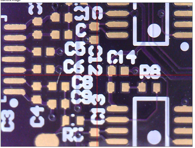
As I was wiring the machine today (for start I mount the original camera) I wanted a solution for a better mounting of the ring led's, because I want my machine to look as lean as possible (i'll share more of my ideas later when there's more progress).
The ring led doesn't fit well on the camera mount; smd resistors or wiring is making contact with the aluminium mount, and I don't like the foam tape solution. I was first thinking of making some bracket with my laser cutter, or some pvc ring would do in between... looking through my workshop I saw the perfect part !!!
I used a soldering wire spool, cut it in half, mounted a rubber ring inside (they are used to protect wires in panel mount) the bigger ring on top of the ring led pcb is to hold the ring led's in place, if you haven't got such a big ring or cannot find them in your local store you could easily use some hot melt glue to keep it in place.

This way you've got your ring led mount and diffuser all in one piece! I didn't power it up yet, but I'm convinced this is the best solution I can think of, by the way: using this 'trick' you've got a second mount as a spare or share ;)

here are some pictures, and please share your feedback with me.
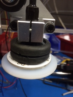
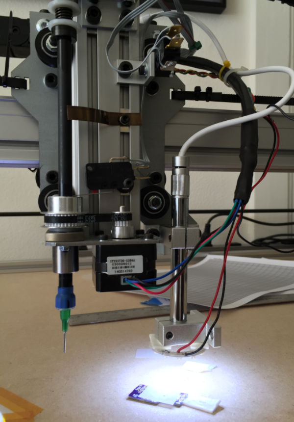
assembly mounted on my machine
IMG_0925.JPG (43.16 KiB) Viewed 22149 times
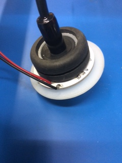
completed assembly
completed assembly
IMG_0922.JPG (40.64 KiB) Viewed 22149 times
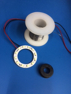
used parts
used parts
IMG_0921.JPG (39.75 KiB) Viewed 22149 times
lilltroll
Posts: 8
Joined: Sat Mar 21, 2015 10:35 am

Re: Better Downward Camea

Post by lilltroll »

Do you have an IC with 0.4 mm pitch ?
If so: How does that look with your camera, and how would the focus look like during a manual placement ? And how does that look with the original upward looking camera ?
The placement will be in 3 steps !?
First to find the center of the IC with the camera, and then to find the center on the PCB with the camera, and last pick and place with the needle!?
Post Reply