Page 1 of 2
FAQ:Machine footprint details
Posted: Thu Apr 27, 2017 10:30 am
by JuKu
Details of the machine footprint, where the needle and camera reach and where is a good area to put the up looking camera hole:
http://www.liteplacer.com/Downloads/Lit ... t_v1_1.pdf.
Edit: Fixed a mismeasurement.
Re: FAQ:Machine footprint details
Posted: Fri Apr 28, 2017 9:24 am
by GilchristT
Perfect timing, I'm starting my build this morning

Thanks
Re: FAQ:Machine footprint details
Posted: Fri Apr 28, 2017 9:28 am
by JuKu
You might be the first that actually puts that drawing in to real use. Please let me know if there are anything unclear, missing or especially, if there are any errors (and apologies for those, if there are any!).
Re: FAQ:Machine footprint details
Posted: Fri Apr 28, 2017 12:04 pm
by mrandt
I disagree with the ideal camera location. Sure, putting it to the left makes use of "dead space" (not visible by head cam).
However, this will increase travel time - if we ever get part aligment with table cam or one decides to go for OpenPNP

I use the left side for nozzle changer and might put auto feeders there ... one fine day...
My camera is in the front of the table about halway down the X-axis.
Basically, my table is organized in four quadrants:
- front left: location for PCB or PCB panel
- front right: trays with parts that require camera aligment, especially larger parts and ICs
- rear left: trays with passives that don't need alignment
- rear right: trays with parts that don't get used very often
This way, when picking up a part that needs alignment, head has minimal travel time when going to camera first and then to PCB.
Just my two cents.
Re: FAQ:Machine footprint details
Posted: Fri Apr 28, 2017 1:43 pm
by GilchristT
With full awareness that this is a newbie disagreeing with the man who designed the machine...
Mrandt's suggestion does seem to make sense. I'd definitely be interested in part alignment and intend to evaluate both the Liteplacer software and OpenPNP.
That said, I've every faith that this won't be my only iteration of the table. I can definitely see a rebuild when John's tape strip holders become available.
Re: FAQ:Machine footprint details
Posted: Sat Apr 29, 2017 10:40 am
by JuKu
Valid points, but camera a few cm to the left of the board is not that far away...
Re: FAQ:Machine footprint details
Posted: Sat Apr 29, 2017 7:12 pm
by mawa
Well have a slightly different layout after I had some ugly crashes when I added the nozzle changer.
I first placed the changer halfway down Y on the left side.
I already had the camera hole at a position resembling the top of an equilateral triangle where the base line is a line from the center of the PCB to the first tape holder (I use mrandt 3D tape holders).
This allows a counter clockwise movement after placing to pick up the next part and optionally be examined by the up looking camera.
Additionally I should mention that I automatically park in the far left corner. When you still have a nozzle attached the head could crash into the protruding changer nuts on the top .
So I relocated the changer to a position right behind the camera hole and on the upper y boundary just far enough to now also let the down looking camera "peek" into the nozzle slot where either a nozzle is unloaded in the slot (the camera sees the black nozzle hole) or the slot is empty (the camera sees the shiny bottom plate of the changer). After changing a nozzle the nozzle can optionally be "inspected" by the up cam before moving to the tape area to pick up a part.
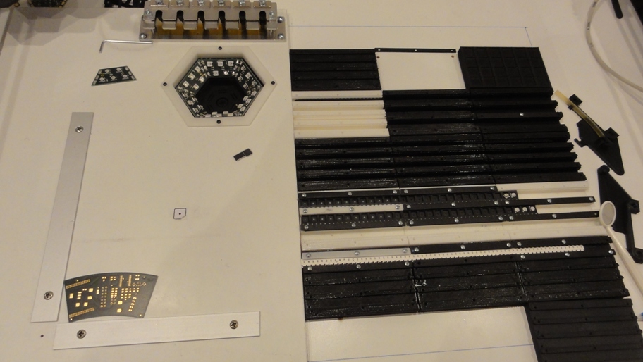
- MaWa Layout
- DSC05263.JPG (198.62 KiB) Viewed 9155 times
I covered the area on the bottom plate with a stripe of yellow capton tape from my 3D printer to get a color contrast.
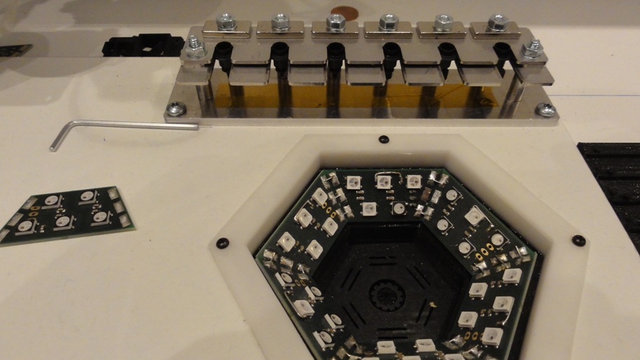
- Location of changer
- DSC05264.JPG (206.2 KiB) Viewed 9155 times
Re: FAQ:Machine footprint details
Posted: Sun Apr 30, 2017 5:14 pm
by GilchristT
Juha
I'm just at the stage of attaching the frame to the table.
It occurred to me that these drawings might be useful to have available in DXF format.
Just a thought.
tommy
Re: FAQ:Machine footprint details
Posted: Sun Apr 30, 2017 6:19 pm
by JuKu
I agree, but I couldn't figure out how to do that in GeoMagic CAD.
Re: FAQ:Machine footprint details
Posted: Mon May 01, 2017 10:34 am
by mrandt
JuKu wrote:Valid points, but camera a few cm to the left of the board is not that far away...
It is not just about distance but also about direction.
With my layout the head picks up part, moves to camera and then advances to the PCB.
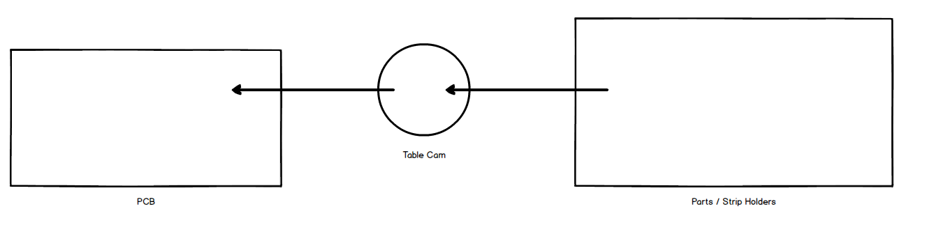
- feeder.png (11.48 KiB) Viewed 9139 times
If you make it move to the other side of the table, it not only travels farther but also has to invert direction. The latter naturally introduces slack and thus additional inaccuracy.
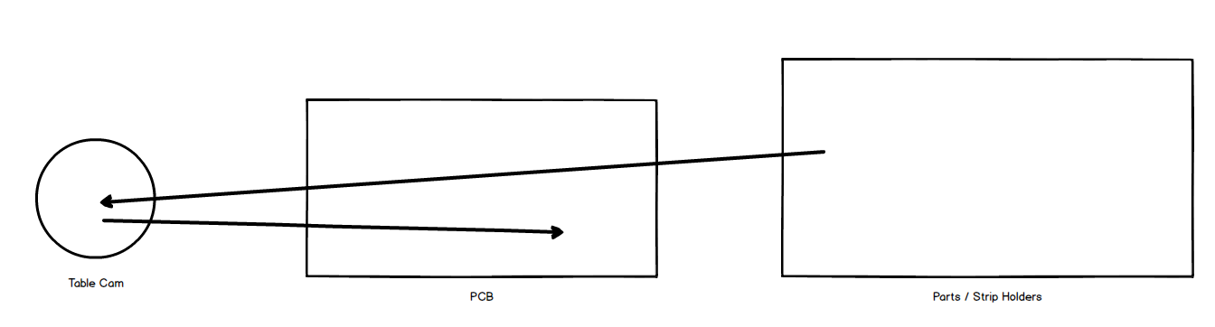
- feeder_2.png (13.84 KiB) Viewed 9139 times