(For kits delivered 2017 or earlier, follow this link)
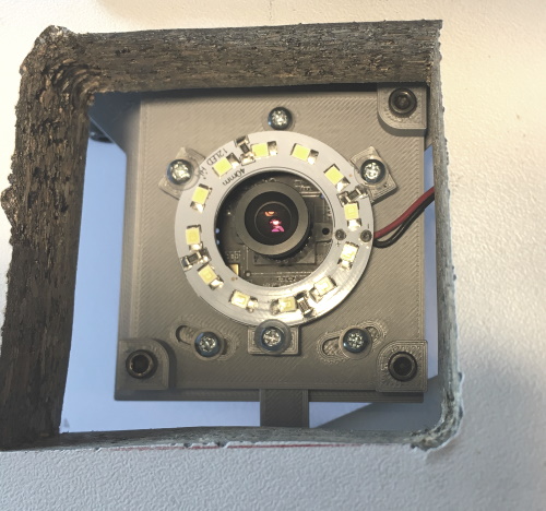
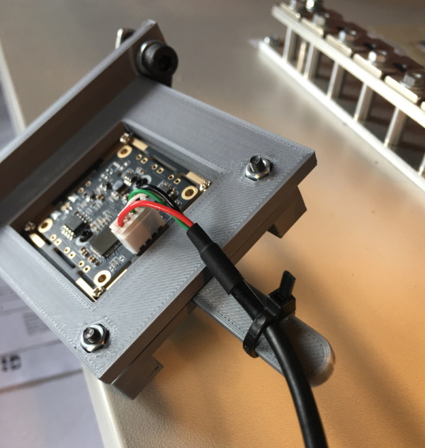
Plug the USB cable to the down camera module. Secure it with a zip tie to the lever in the assembly. Using the screws supplied with the camera, install the camera assembly to the lower slot of the holder, opposite side of the bracket. Attach the extrusion under your table so, that all screws on the top side of the camera assembly are visible and accessible from the hole. The lever in the assembly should point towards the front of the table. Please see the image below.
Here is an image of the camera cable attachment and securing:
Optional: Nozzle Shade
Software improvements make this section obsolete. Please have a look anyway, so you know what to do, if you find a shade might be useful:
We need to hide the tube attachment parts from the up-looking camera; the camera should see only the nozzle tip. Use the supplied shade material and and attach a shade to the bottom of the rotation motor. Here is mine:

To help for these, here is a customer supplied design (DXF file) for a template and a PDF for the same (thank you very much!). The round thing on the template refers to the older version of the machine, please ignore that. If you want to design your own, here is an outline of the relevant parts. The T shaped part with a hole in it is the old model camera holder, ignore this. the other parts are the Z axis extrusion and the edge of the motor holder plate. These move, so you want to have some clearance to them.
Previous –
Current kits (delivered after June 2021): Next
Kits delivered before June 2021: Next