Using 3d printed part holders

Stencils, paste, ovens, ...
Post Reply
JuKu
Site Admin
Posts: 1110
Joined: Thu Feb 14, 2013 3:06 pm
Location: Tampere, Finland
Contact:

Using 3d printed part holders

Post by JuKu »

I've experimented with 3d printed part holders, and this is what I use. I got the idea from the net somewhere, but I forgot to take a bookmark. But the idea itself was so simple, that I did not forget it. For proper credit, I'll appreciate a link to the origin of this.

The basic idea is that a holder with just the right dimensions is tight enough to keep parts in place during use, but loose enough to be able to slide strips in. And the idea works:
Image

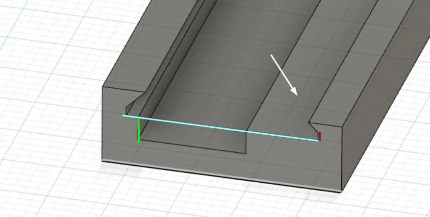
The width (blue line) and the slot (red line) before the edges start to go inwards are the critical dimensions here. The component slot depth (green line) is just deep enough that parts are supported from the bottom. This support is needed, otherwise they fly off when parts are picked up. For small parts like resistors, there would be no slot. The surface the white arrow points at, needs to be smooth. I use ironing function on Prusa slicer, I’m sure other slicers have similar capability.

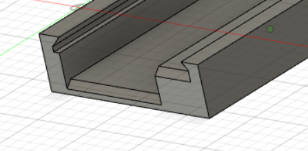
On some holders, I have small chamfers to ease sliding the tape in:
Image

The good:
-Cheap
-Easy and fast to print
-Stays on board with double sided tape
-Works very well.
-Tape can be put in with the cover tape on, peeling does not gets parts flying. Peel just a little of the cover tape before sling the tape in, so there is something to grab onto, and support the tape with a finger when peeling.

The bad:
-The dimensions are tight for the idea to work. Unfortunately, there is too much variation in tapes that one set of dimensions are sufficient. I ended up with three profiles for small components (no component slot): Thick paper tape, thin paper tape and plastic tape. And when you have tapes that need the component slot, this gets worse. I gave up early trying to manage this. Instead I used very short trial parts to get the dimensions right, and when I need new type of holder, I make trials. When you get a hang of it, you’ll get it right on the first or second try, and these print fast. And when you get one right, why not print a few for the next ones? I have (currently) two cups of holders, so I’m likely to have a suitable one for new components. (The variation needed is the reason why I don’t offer these in my shop.)

-The cameras I use have limited depth focus at short distances. Therefore I recommend making your whole setup* so, that both PCB and component holders top surface (the surface pointed by the white arrow) are elevated from the work surface. I think that 10mm or so would be sufficient for most cases. Capacitors are the tall parts, but nowadays even those are not very tall. (On the other hand, in my previous job we used a lot of surface mounted relays…)

*: I haven't actually done this, as I haven't had a project that uses parts that would make me to do this, nor have I modified my machine so that it would need a recalibration.

Data:
My data for these is here (Fusion 360): https://a360.co/3FcnAof. However, even if you don’t have Fusion or don’t know how to use it, the idea is simple, you can draw it in CAD of your choice in minutes.
liteyear
Posts: 8
Joined: Fri Jun 02, 2023 7:01 am

Re: Using 3d printed part holders

Post by liteyear »

Oh this is perfect timing! Having just finally assembled my LitePlacer and going deep into research into the layout of the bed, you've answered several burning questions I had.

After painstakingly calibrating the heck out the machine at precisely 1.6mm above the surface, I've had a niggling feeling I'm going to be better off 10mm higher. Not just for tall components but also to be able to mount things to the bench top (eg on 2020 rails). But I do worry about holding the pcb flat and firm at that height. It's very convenient to just drop bare pcbs on the table surface and slide them over to a fixed guide at a known location. Any ideas on that? Maybe just a sheet of flat timber to act as a tray?

And as far as inspiration for holders, I have a long list I've been studying. A summary, for reference:
Yours are like a cross between Pat Deegan's and zubin3333's I suppose, but several of the others have similar themes.

I've been desperately looking for a starting point and I think yours is it! A lot of clever thought and iteration has gone into Pat's, but I have the advantage of a printer at my disposal to do test prints like you describe, and I'm leaning towards your no-sharp-overhang design.

One aspect of the design I'm undecided on though, is whether compliance is beneficial. mgrl's and derivatives use a flexible edge to apply friction and accommodate tolerances. Perhaps the slight horizontal compression it would apply would be more trouble than its worth, and I'm better off tuning the print (eg. the ironing you suggest) to get a neat fit.

And finally I wonder about repeatable pick locations. I think it would be beneficial to be able to drop the holders on the table and slide them to guides that create consistent pick locations. I don't want to gunk up my table with tape, but I think some glue I can clean off might help keep them in place.
liteyear
Posts: 8
Joined: Fri Jun 02, 2023 7:01 am

Re: Using 3d printed part holders

Post by liteyear »

So far so good. I started with your Fusion360 file and experimented with a few different tapes. My sample set of tapes is small, but I was able to reduce the number of dimensions that have to change between tapes down to the tape width, the tape thickness and the depth of the tape embossing.

I then had a snug fit using these parameters:
Screenshot 2023-06-19 at 4.25.59 pm copy.png
Screenshot 2023-06-19 at 4.25.59 pm copy.png (197.02 KiB) Viewed 34431 times

The three dimensions are in the last column. You can see I ended up with just a width/thickness combo for paper and for plastic, and only the depth has to be configured for plastic tapes. That's a bit of trial and error, but at least it's only one parameter, and it's only ~10 minutes of printing between trial runs.
IMG_6114.jpg
IMG_6114.jpg (485.81 KiB) Viewed 34431 times
I'll continue experimenting and start to build up some sets.
JuKu
Site Admin
Posts: 1110
Joined: Thu Feb 14, 2013 3:06 pm
Location: Tampere, Finland
Contact:

Re: Using 3d printed part holders

Post by JuKu »

For real use, you probably want to ironing on the surface that is visible through the holes - or not, “kill color” vision processing function might work well on that color. I didn’t have any suitable filament with that bright color to try.
liteyear
Posts: 8
Joined: Fri Jun 02, 2023 7:01 am

Re: Using 3d printed part holders

Post by liteyear »

Oh yeah. I did mean to apply ironing but forgot, and then found it was smooth enough. But I didn't think of the uneven reflection! That will certainly help with vision.

Here's the latest iteration. Coming together nicely. I have a table guide in silver that has notches to snugly accept the part holder tray. For now, this tray has 6x 8mm paper and 2x 8mm plastic slots (with ironing this time!). It has wings at one end that tessellate with the next tray.
IMG_6115.jpg
IMG_6115.jpg (3.02 MiB) Viewed 34413 times
The bite out of the bottom left corner shrouds my homing mark, so the whole thing can be glued to the desk, protecting the homing mark and providing fixed locations for 8 tapes and the PCB origin. I can slide the trays in and out to facilitate off-table loading, and rotate them to suit the job.

At least that's the theory! Seems to work nice just mucking around. But it will be shortly put to the test on a small production run.
Post Reply