Logitech C270 3D printer brackets

Post Reply
Inakto
Posts: 1
Joined: Fri Nov 04, 2016 12:39 am

Logitech C270 3D printer brackets

Post by Inakto »

Hello,
I am using the Liteplacer with OpenPNP and I upgraded the down camera to the logitech c270.

The image is much better, and the glare is significantly less.

To attach it to the liteplacer, I designed two 3D printed parts. I am sharing these here in case they are of use to anyone.


Jonathan.
6514844269692757049-account_id=1.jpg
6514844269692757049-account_id=1.jpg (203.17 KiB) Viewed 12138 times
c270_liteplacer.zip
(399.99 KiB) Downloaded 777 times
JuKu
Site Admin
Posts: 1110
Joined: Thu Feb 14, 2013 3:06 pm
Location: Tampere, Finland
Contact:

Re: Logitech C270 3D printer brackets

Post by JuKu »

thank you for sharing! Here is a smaller image that hopefully scales better for small (mobile) displays.
Image

Also, let me move this thread (originally in the OpenPnP section), as this is useful for people not using OpenPnP as well.
mawa
Posts: 139
Joined: Wed Jun 10, 2015 1:23 pm
Location: Near Hamburg, Germany

Re: Logitech C270 3D printer brackets

Post by mawa »

I ruefully returned back to the original camera solution after trying to get the down cam recognition to work with the c270.

Main problem: the depth of field.

Using maltes tape strip feeders my components are approx. 10mm above the table.
The PCB is on the table so the printed surface is approx. 1.6mm above the table.
The homing circle is a black nailhead approx. 1mm above the table.

I tried to adjust the camera lens and the camera height to achieve sharp images on all three levels. No success.

So I raised the board and zero circle level to 10mm.

Now to image was sharp and clear. I carefully adjusted the mm/pixel.

But the circle recognition war very slugish and came with many stray locations.
Homing worked 1 of 3 times.
Fiducials: had problems with the left top most one. Maybe because of the white table area visible above the PCB board. I don't know.

Minor problem: the camera touches the y axis belt on the right when you move to machine max X.

After spending several days I reinstalled the 10mm Juha CAM, took away the PCM 10mm elevation and carefully adjusted the camera at its down most position.

Now homing always takes only 2-3 iterations. Fiducials: all 4 with 2-3 iterations.

These are just my experiences. You do have to carefully determine the correct mm/pixels. And maybe the cause for the bad circle recognition is the missing Camera lens calibration that openPnP has.
best regards
Manfred
JuKu
Site Admin
Posts: 1110
Joined: Thu Feb 14, 2013 3:06 pm
Location: Tampere, Finland
Contact:

Re: Logitech C270 3D printer brackets

Post by JuKu »

That could be improved in software, I think (I need to try). Currently, it doesn't really handle other resolutions than the standard cameras, but there is really no point to process all of the image when doing most measurements; if the circle we are looking for is not near the center to begin with, there is an issue.
mawa
Posts: 139
Joined: Wed Jun 10, 2015 1:23 pm
Location: Near Hamburg, Germany

Re: Logitech C270 3D printer brackets

Post by mawa »

JuKu wrote:That could be improved in software, I think (I need to try). Currently, it doesn't really handle other resolutions than the standard cameras, but there is really no point to process all of the image when doing most measurements; if the circle we are looking for is not near the center to begin with, there is an issue.
Having spent additional time trying to calibrate the camera I also had the following observation:

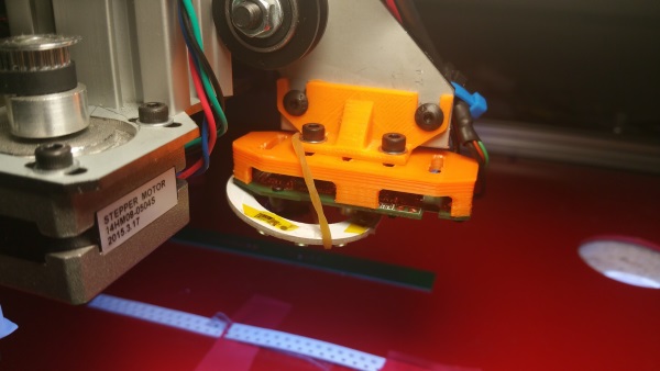
As reported I am using maltes strip feeders, which are 10mm above the table surface.

I first adjusted the pixels/mm value for the table surface using a precision steel ruler by clicking on the ruler ticks and observing the resulting position. Within a range of +/- 15mm the results could be calibrated very good.

Then I observed that trying to position the down cam to a location on the elevated tape did not work properly. I brought the ruler into view and the values of course were different!

So the conclusion is to bring ALL objects you intend to measure / calibrate to the same Z level.
best regards
Manfred
GilchristT
Posts: 10
Joined: Wed Apr 26, 2017 12:04 pm

Re: Logitech C270 3D printer brackets

Post by GilchristT »

Thanks for this Inakto

I've picked up a C270 and will print the brackets tomorrow.

I'm using cable management chains and the USB cable doesn't look like it'll reach through the loops to the Z-axis.

Do you use cable chains? Did you extend the USB cable on the webcam?

thanks

tommy
mrandt
Posts: 407
Joined: Mon Apr 27, 2015 10:56 am
Location: Stuttgart, Germany

Re: Logitech C270 3D printer brackets

Post by mrandt »

Nice 3D printed part :-)

I particularly like the fact that you can adjust for camera tilt along the X axis (cam might be tilted around Y axis).

This got me thinking... The C270 camera board is rather flat, so we could attempt to move it below the Gantry - thus reducing the offset between nozzle and cam and increasing the usable area.

I will have to give this some more thought.

Regarding the depth of field / focus issue: I have moved everything to the same height; strip holders, PCB brackets, even the optical homing mark is elevated to that level. It sits ona small cube with a sticker on it.

This way I don't have any issues with focus; it also makes sense because it is the only way to make pixel-to-mm ratio consistent.
Michael_N
Posts: 24
Joined: Tue Aug 30, 2016 5:18 am

Re: Logitech C270 3D printer brackets

Post by Michael_N »

Hi
I know this is an old topic, but I'm considering replacing the down view camera with the C270. So I was wondering if anyone has some experience with this cam, that can they can share?

Kind regards
Michael
Post Reply