Page 2 of 2
Re: Placing ICs (Video)
Posted: Wed Apr 27, 2016 8:38 am
by mawa
Flavor wrote:That's a good thought. I hadn't considered that it might have some inertia on the spin.
I am trying to place 5050 RGB LEDs and found that the friction of the needle tip with the clear plastic cover window is very low.
I have to rotate the LEDs from their 0 degrees tape orientation up to 180 degrees.
Although the A drive is relatively slow I irregularly encounter off angles of up to 5 to 10 degrees, which seem to result from rotation inertia.
Additionally this rotation occurs during XY movement which could add slight vibrations to the pickup tube and thereby lowering the friction.
The tape pockets are also a bit too large which allows the LEDS to have a start angle difference which add up to a not acceptable angle displacement.
I tried using the rubber cup Juha has added to the kit but the diameter is too large.
The same problems seem to occurs with ICs and their mass is truely larger that the 5050 LEDs.
Looking at professional P&P machines you will see that they all use suction cups with 3mm or more for picking ICs. So IMHO going to JUKI or Samsung tips is the meaningful direction.
Re: Placing ICs (Video)
Posted: Wed Apr 27, 2016 11:57 am
by mrandt
Hi Manfred,
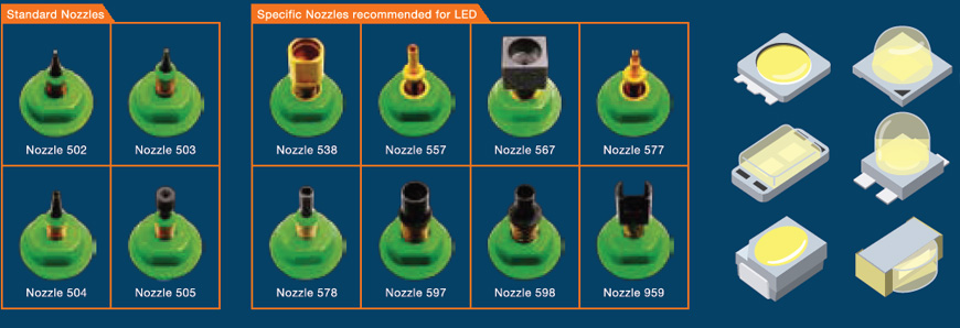
Juki has special nozzles for LED, see here:

- juki_led_nozzles.jpg (96.87 KiB) Viewed 8488 times
I have not found special LED nozzles for Samsung CP40 but maybe I just need to look harder...

Cheers
Malte
Re: Placing ICs (Video)
Posted: Wed Apr 27, 2016 4:48 pm
by Flavor
We have tried the suction cup on the tip. It is definitely better. It also helps in the up camera's view of the needle tip, as we just slide the suction cup up when placing the 0603 and 0402 discreet components. I guess that's a nice little bonus. I don't know that this is a great final solution, but it's a good one for the moment. We might move to trying some of the Juki nozzles, as it sounds like those are quite a bit better.
One thing we've noticed is that the parts we place from the "loose part" area do better than the flash chips that come in a tape/reel. If we put a flash chip in the loose part area, it seems to place it better. There are several downsides to this, but one (maybe less obvious) one is that the flash chip is almost too big for the down camera. It just fits in the viewing window, so it needs to be placed in the loose area pretty perfect.
The flash chips we use are fairly loose inside of their tape. There is definitely enough play for the part to be off by a whole pin (as the parts are fairly tight pin pitch).
Is there any good way to make the LitePlacer use the down camera (or the up camera) to detect the chips that come in a tape/reel?
Re: Placing ICs (Video)
Posted: Wed Apr 27, 2016 5:21 pm
by Pixopax
Mark Harris wrote:If it can do 0402 it can certainly do something with pitch that size.
TSOP and 0402 is a big difference:

- tsop28.jpg (9.57 KiB) Viewed 8482 times
Left: 0402, right: TSOP
I am very sure that you will not be able to place that reliable, first because they are not straight in the tape, second because the pitch is just too small and the package too wide.
Avery slight angle mismatch will result in a large pad misalignment.
That will only be possible with upcam support, which the software does not have yet.
Besides of that: Your paste printing is to bad for these finepitch parts. I had these problems often when the stencil was to thick, or when the pcb bended down when printing due to the pressure I gave to the Squeegee.
You should first try to get that done correctly, as you will have lots of shorts with that much solderpaste on the board.
Re: Placing ICs (Video)
Posted: Wed Apr 27, 2016 5:28 pm
by Flavor
Pixopax wrote:Mark Harris wrote:If it can do 0402 it can certainly do something with pitch that size.
TSOP and 0402 is a big difference:
Yes, the other big difference is that an 0402 part has 2 solder points that are on opposite sides. If the piece is not rotated properly, it will still function. In fact, the soldering process may "pull" it onto the pad.
Our TSOP has 40 pins. If it is off a bit, it may actually be contacting a neighboring pad, and the soldering process will not pull the chip.
Having said this, the suction cup did help. Using the loose part area also helps.
It is still not good enough to just PnP and then solder. We need to inspect and re-align before soldering.
Pixopax wrote:Besides of that: Your paste printing is to bad for these finepitch parts. I had these problems often when the stencil was to thick, or when the pcb bended down when printing due to the pressure I gave to the Squeegee.
You should first try to get that done correctly, as you will have lots of shorts with that much solderpaste on the board.
This is correct. Actually, the PCB fab sent us the wrong stencil. They created it from the solder mask layer, but we had given them a stencil layer. They are fixing the problem. Our stencil layer has smaller cutouts to give us less paste. I hope that helps, but we do not have it here, yet. We will just wick the excess by hand in the meantime.
What other tips can we try for properly placing the part?
Re: Placing ICs (Video)
Posted: Fri Apr 29, 2016 1:07 am
by Mark Harris
Flavor wrote:Mark Harris wrote:We bought Juki nozzle clones, they are pretty popular in the open source community - i think mostly because of easy availability.
http://www.aliexpress.com/item/SMT-JUKI ... 9e5810c7f7
Is the seller I bought from - very fast shipping and all the nozzles are within 0.01mm of each other for the critical dimensions.
I'm building a dual head machine, and have 2x 502, 2x 503, 2x 505, 1x 505, 1x 508 to handle the range of ICs and passives which I'll be using.
Hey Mark. I finally had a chance to sit down and look at these. How do you attach these tips to your LitePlacer? Do you have some sort of quick-disconnect? Could you post some photos of your nozzle/tip setup? That would be excellent.
Thanks!
I have a quick disconnect I designed that I printed on one of the polyjet SLA printers at work, for NEMA11 motors - I don't have a liteplacer

0402 pads are relatively large, but the placement size is quite small and Juha has shown that the machine is quite capable of hitting dead centre on the pad - so the machine is mechanically capable of placing the part you want. I think you should use up vision to correct the part centre/rotation if its that bad in the tape pocket.
Re: Placing ICs (Video)
Posted: Wed May 04, 2016 12:11 pm
by Gabriel
Speaking of LEDs, has anybody successfully placed or a suggestion for the choice of the nozzle for OSRAM's SIDELED series:
http://www.osram-os.com/osram_os/en/pro ... /index.jsp
I've not yet tried to place them, I was just looking for advice. Precision is not a problem, but they are quite asymmetric in terms of weight distribution.