Page 4 of 11

Re: Tape Strip Holders

Posted: Mon Nov 14, 2016 11:30 am
by JuKu
And at least my biggest suggestion is to let you inspired by shifting tapes in tray: https://youtu.be/XIKzpkfqq60?t=55s. This solution are totaly appropriate for liteplace. Easiest way how to make a automatic feeder, which can be next big progress for litplacer. There are also option to combine this 2 solutions and eq. you place 10 components and then p&p shift tape in tray to save more time. It's depend on pressure of spring you use in you modular tray system.
Peeling the tape is probably the biggest difference, and solving that would certainly increase the price.
I agree. By my experience, you can't really move the tape if the tape is not on. Small parts weight about nothing, and slight vibration would throw them off. Even if the holder grip is tight and the surfaces smooth enough that the tape can be advanced in the holder, then either there needs to be a solution to peeling the cover tape or the cover tape is already manually peeled - in which case, the peeled section of the tape needs to be already fully in the holder, so no need to shift it by the machine.

I think we should (at least, at the first iteration) have holders that hold the tape tight, so that picking up a part or peeling the tape does not throw parts away. The way I see this working is that the holders are chainable or the software understand that there can be same parts on multiple holders, or both. Before a run, the software checks that you have enough parts on the table. If not, you manually advance the tape(s) and peel the cover tape. The software does not do these things yet, but it should; the point is that you should be able to set up a run, start it and go away.

Re: Tape Strip Holders

Posted: Mon Nov 14, 2016 3:08 pm
by mrandt
JohnSL wrote:[...] I also finally added a pin for positioning the tape
I like the "clip" with the sprocket hole alignment pin :-D

Would you consider adding a small flag to that clip which could carry a QR-code for feeder identification? If not, where to put such code?

Also I still think that adding some sort of fiducial marker at each end of the feeder would make sense; but I am not sure about the best way to achieve this. One way could be to have a clip at each end, another to incorporate the markers in the side rails.

I think that detecting the sprocket holes is a suboptimal solution. It is great and necessary if you just tape the strips to the table. But if you have a feeder like John's, it would be much easier and less prone to errors to detect some visual marker at each end of the feeder and deduct part location, spacing etc. from their locations.

Together witha unique QR code on the feeder, this would allow to "auto setup" known parts in software and thus greatly reduce setup time...
instrukcion14 wrote:And at least my biggest suggestion is to let you inspired by shifting tapes in tray: https://youtu.be/XIKzpkfqq60?t=55s. This solution are totaly appropriate for liteplace. Easiest way how to make a automatic feeder, which can be next big progress for litplacer.
I think we need to make a clear distiction between strip feeders and (semi) automatic feeders. John's design is certainly the first and will be more than appropriate for most prototypes, where you usually only need (and buy) a small quantity of each part.

Automatic feeders are a totally different story. First of all, they are only necessary if you want to populate larger quantities of boards. This could be done but is per Juha's definition not the purpose of LitePlacer.

If you truly need auto-feed, there are many different approaches in the extended community of DIY Pick and Place.

Most of the "drag feeders" (as shown in the video) suffer from issues with cover tape removal. It is also not advisable to advance the tape using the nozzle; instead a solenoid-activated pin should be mounted on the head. I don't think this is the best way to go - and will certainly not work with John's strip feeders.

Many people use commercial PNP feeders, often second-hand and sometimes with modifications - which is expensive.

In the DIY space, I would distinguish three different types:

1. Mechanically actuated feeders, which advance the tape after being triggered by the head (head pushes a lever), e.g. Karl Ekdahls feeder http://www.knasmusic.com/diyeverything/ ... eeders.php or Alex's feeder https://github.com/alexavr2/alexfeeder or this promising work in progress https://groups.google.com/forum/#!topic ... g57XAz-_IA - with all these approaches you still need a mechanism to pull off the cover tape

2. Motorized feeders which advance the tape by pulling the cover tape, e.g. Volker's https://www.vbesmens.de/en/pick-and-pla ... eeder.html

3. Motorized feeders which advance the tape by the sprocket holes using a toothed wheel (like commercial feeders) and remove the cover tape, e.g. Protovoltaics feeder https://youtu.be/uNBV_dabrDA?t=28s or Chipsetter's feeders http://www.chipsetter.com/one/ which are said to be sold seperately at some point - however I don't know of any successful, open-sourced builds in this space

I'd advocate to keep things seperate.

John and Juha are attempting to make a strip feeder which should be affordable in larger numbers, which is great for prototyping and small volume manufacturing and will (maybe combined by some new and clever software features) reduce setup time significantly.

If instrukcion14 or others want auto feeders, this should be an independent project.

Just my €0,02 ;-)

Re: Tape Strip Holders

Posted: Mon Nov 14, 2016 6:21 pm
by mawa
Working with mrands 3d printed tape holders with 5050 LEDs in a black plastic tape I found that it is essential to have a bottom support just below the bottom of the tape pocket.
Having the pockets float in mid air - only supported by the tape stripes - inevitably leads to "jumping" parts when you pickup a part using any kind of probing.

Is such a support provided?

Re: Tape Strip Holders

Posted: Mon Nov 14, 2016 7:26 pm
by JuKu
You can manually set pickup z. Does that help?

Re: Tape Strip Holders

Posted: Tue Nov 15, 2016 9:47 am
by mawa
JuKu wrote:You can manually set pickup z. Does that help?
Sure the second pickup after probing works fine even if Z can be a bit lower than necessary due the plastic tape give way.

But using the probing function is very nice and comfortable. Testing the new nozzles I use manual pickup and placement at the down cam location and pickup parts from different locations (tape, PCB, tabletop).

Re: Tape Strip Holders

Posted: Tue Nov 15, 2016 2:50 pm
by mrandt
mawa wrote:But using the probing function is very nice and comfortable.
Agreed, but it also causes issues. The force required to trip the probing switch was about 3.6N on my machine. That is enough force to dent electrolytic caps or crush embossed tapes in strip holders.

I have experimented with alternative sensors for Z-probing which might be less "brutal" but have not found a satisfying solution yet.

For this reason, I am manually setting Z-level for pickup (and sometimes also for placement). Also, with tape strip feeders, all pickup heights are the same - so there is no need to "probe" these. Just figure out the correct Z-coordinate once and use it on all feeders...

OpenPNP does not support auto probing either; so if you chose that software, you have to set Z-levels yourself anyway...

Re: Tape Strip Holders

Posted: Thu Nov 17, 2016 7:21 am
by JohnSL
Hi everyone,

I've had a busy week at work, so it took me a while to write a response. Here is a list of the things I still need to address:
  • A place to add a QR code or other form of identification
  • Fiducial marker (questions below about this)
  • Better tape alignment (explained more below)
I also have some specific questions.
mawa wrote:Working with mrands 3d printed tape holders with 5050 LEDs in a black plastic tape I found that it is essential to have a bottom support just below the bottom of the tape pocket.
Having the pockets float in mid air - only supported by the tape stripes - inevitably leads to "jumping" parts when you pickup a part using any kind of probing.
I haven't used Malte's feeder (I guess I should print it out and try). When you have the LED tapes in that holder, how firmly does it hold the edges of the tape? I have several different thin black tapes loaded into my 3D printed feeders (that have the same type of design for pushing up from the bottom). With these tapes, I can poke a lot on other parts right next to where the tape has been peeled off, and I don't get parts bouncing out of the tape.

About the fiducial markers. I could certainly include some feature in the injection molded part. How well could the camera pick this up, though, if it's the same color as the rest of the strip holder? In other words, I'm still not sure how to handle this.

There is one thing Juha pointed out to me. I had to make the tape opening slightly wider (0.3 mm) to allow for the maximum tape width that is 0.3 mm wider than advertised. In other words, an 8 mm tape can be up to 8.3 mm wide. I made the opening 0.4 mm wider so there would be some clearance for the widest tapes. However, this means that a tape that is actually 8 mm wide might not be aligned exactly in the slot. Instead it could be off by +- 0.2 mm. I have an idea that I think will work with injection-molded only parts, so it won't increase the cost. I have to try it out in CAD, and then 3D printed prototypes, before I'll be sure it works well.

Finally, Juha had a question about the color of plastic. I did some research, and ESD plastic is available in natural ABS, which can be dyed different colors. So I think there is a good chance I'll be able to have the parts made in green (I'm thinking a lighter green like used for green screens in the film industry).

Re: Tape Strip Holders

Posted: Thu Nov 17, 2016 1:28 pm
by mawa
JohnSL wrote:
mawa wrote:Working with mrands 3d printed tape holders with 5050 LEDs in a black plastic tape I found that it is essential to have a bottom support just below the bottom of the tape pocket.
Having the pockets float in mid air - only supported by the tape stripes - inevitably leads to "jumping" parts when you pickup a part using any kind of probing.
I haven't used Malte's feeder (I guess I should print it out and try). When you have the LED tapes in that holder, how firmly does it hold the edges of the tape? I have several different thin black tapes loaded into my 3D printed feeders (that have the same type of design for pushing up from the bottom). With these tapes, I can poke a lot on other parts right next to where the tape has been peeled off, and I don't get parts bouncing out of the tape.
Your question gives the answer to the jumping. When I used the holders without suitable support below the pockets the tape was not fixed very well at its edges. Therefore the downward probing pressure led to a bending kind of deformation that snapped back when the head move back up.

Re: Tape Strip Holders

Posted: Thu Nov 17, 2016 2:47 pm
by mrandt
mawa wrote:Your question gives the answer to the jumping. When I used the holders without suitable support below the pockets the tape was not fixed very well at its edges. Therefore the downward probing pressure led to a bending kind of deformation that snapped back when the head move back up.
Don't get hung up on my feeder design - I think John's mechanism to hold the tape is superior to my approach. With my feeders the fixation of the tape depends on fastening the screws carefully; in John's design this is overcome by the spring and slider mechanism. Bottom line is: If the edges of the tape are well supported and pressed against the top rail with sufficient force, I don't think we will see issues with vibrations and "jumping" parts.

I also think that the probing force is too strong; so manually setting Z-level for pickup (which would be identical for all strip feeders anyway) could reduce the problems.
JohnSL wrote:About the fiducial markers. I could certainly include some feature in the injection molded part. How well could the camera pick this up, though, if it's the same color as the rest of the strip holder? In other words, I'm still not sure how to handle this.
To detect a feature visually, it needs to have some contrast relative to its background. Where would you put such feature? I think circular would be best as it is easy to visually find the center of a circle...

Ideas:
- Could we have an indentation on the feeder and colour this later (thinking black fine marker or similar)?
- Other option would be to mold a small cylindrical "pin" in different color and press fit this into the side wall.
- Third option I could think of would be to have a "snap on clip" (like for the sprocket hole index pin) on both sides of the feeder; this clip could also hold fiducial markers. So front clip would have a tab for QR code and fiducial, back clip only fiducial.

Edit: Now that I think about it, option 3 might be the best - as that clip could serve more purposes as outlined below.
JohnSL wrote:I made the opening 0.4 mm wider so there would be some clearance for the widest tapes. However, this means that a tape that is actually 8 mm wide might not be aligned exactly in the slot. Instead it could be off by +- 0.2 mm.
I think that at the front end the index pin makes sure the tape is in the right location, both left / right and back / forth. Sprocket hole vs. part pocket location is usually a very tight tolerance. So why not add a similar clip at the back end of the feeder as well?

This secondary clip (and the holding features in the side walls) could be made in such a way that the clip could slide back and forth. The sliding would be necessary as there is some tolerance in sprocket hole spacing (in tape direction), too. If we could slide the clip even further, we could support shorter tape strips.

Both clips together would nicly align any tape strip parallel to feeder orientation; as the front clip would be fixed, it would ensure the first part position.
JohnSL wrote:So I think there is a good chance I'll be able to have the parts made in green (I'm thinking a lighter green like used for green screens in the film industry).
I'd vote for black side walls, spacers and clips - just because it looks better. Only the sliding support rails should be green - if at all. I still doubt that we need to visually detect the sprocket holes once we have auto setup in software. Detecting fiducials and QR code on the feeder sounds more reasonable to me.

Last point about sprocket holes: When I designed my feeder, I had some trouble with the tolerances of the rails which are meant to hold down the tape. I did not want to cover the sprocket holes, but still wanted a tight hold on the tapes.

I ended up with the following:
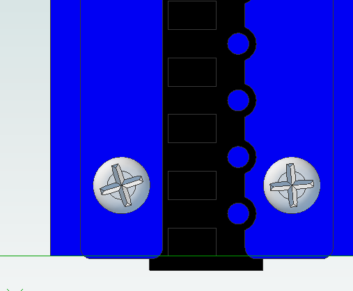
feeder_cutouts.png
feeder_cutouts.png (22.8 KiB) Viewed 22540 times
feeder_side.png
feeder_side.png (25.68 KiB) Viewed 22540 times
I think you might run into similar problem. Making the rails wider means the tapes will be held more firmly; but might cover the sprocket holes.

IMHO this also supports my argument for ficudials on the feeder itself; because if we had those and the software supported it, we would not have to care about the sprocket holes being visible.

Even if fiducials were not visible, we could still "teach" the software the first and last part location - this is how most commercial machines are being setup for strip feeders.

Re: Tape Strip Holders

Posted: Thu Nov 17, 2016 3:19 pm
by JuKu
> I did some research, and ESD plastic is available in natural ABS, which can be dyed different colors.

Cool, I thought ESD would be black only.

> Even if fiducials were not visible, we could still "teach" the software the first and last part location

The software can do this already.