Using 3d printed part holders
Posted: Thu Jun 15, 2023 2:41 pm
I've experimented with 3d printed part holders, and this is what I use. I got the idea from the net somewhere, but I forgot to take a bookmark. But the idea itself was so simple, that I did not forget it. For proper credit, I'll appreciate a link to the origin of this.
The basic idea is that a holder with just the right dimensions is tight enough to keep parts in place during use, but loose enough to be able to slide strips in. And the idea works:

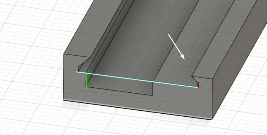
The width (blue line) and the slot (red line) before the edges start to go inwards are the critical dimensions here. The component slot depth (green line) is just deep enough that parts are supported from the bottom. This support is needed, otherwise they fly off when parts are picked up. For small parts like resistors, there would be no slot. The surface the white arrow points at, needs to be smooth. I use ironing function on Prusa slicer, I’m sure other slicers have similar capability.
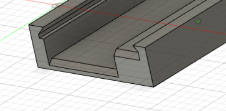
On some holders, I have small chamfers to ease sliding the tape in:

The good:
-Cheap
-Easy and fast to print
-Stays on board with double sided tape
-Works very well.
-Tape can be put in with the cover tape on, peeling does not gets parts flying. Peel just a little of the cover tape before sling the tape in, so there is something to grab onto, and support the tape with a finger when peeling.
The bad:
-The dimensions are tight for the idea to work. Unfortunately, there is too much variation in tapes that one set of dimensions are sufficient. I ended up with three profiles for small components (no component slot): Thick paper tape, thin paper tape and plastic tape. And when you have tapes that need the component slot, this gets worse. I gave up early trying to manage this. Instead I used very short trial parts to get the dimensions right, and when I need new type of holder, I make trials. When you get a hang of it, you’ll get it right on the first or second try, and these print fast. And when you get one right, why not print a few for the next ones? I have (currently) two cups of holders, so I’m likely to have a suitable one for new components. (The variation needed is the reason why I don’t offer these in my shop.)
-The cameras I use have limited depth focus at short distances. Therefore I recommend making your whole setup* so, that both PCB and component holders top surface (the surface pointed by the white arrow) are elevated from the work surface. I think that 10mm or so would be sufficient for most cases. Capacitors are the tall parts, but nowadays even those are not very tall. (On the other hand, in my previous job we used a lot of surface mounted relays…)
*: I haven't actually done this, as I haven't had a project that uses parts that would make me to do this, nor have I modified my machine so that it would need a recalibration.
Data:
My data for these is here (Fusion 360): https://a360.co/3FcnAof. However, even if you don’t have Fusion or don’t know how to use it, the idea is simple, you can draw it in CAD of your choice in minutes.
The basic idea is that a holder with just the right dimensions is tight enough to keep parts in place during use, but loose enough to be able to slide strips in. And the idea works:

The width (blue line) and the slot (red line) before the edges start to go inwards are the critical dimensions here. The component slot depth (green line) is just deep enough that parts are supported from the bottom. This support is needed, otherwise they fly off when parts are picked up. For small parts like resistors, there would be no slot. The surface the white arrow points at, needs to be smooth. I use ironing function on Prusa slicer, I’m sure other slicers have similar capability.
On some holders, I have small chamfers to ease sliding the tape in:

The good:
-Cheap
-Easy and fast to print
-Stays on board with double sided tape
-Works very well.
-Tape can be put in with the cover tape on, peeling does not gets parts flying. Peel just a little of the cover tape before sling the tape in, so there is something to grab onto, and support the tape with a finger when peeling.
The bad:
-The dimensions are tight for the idea to work. Unfortunately, there is too much variation in tapes that one set of dimensions are sufficient. I ended up with three profiles for small components (no component slot): Thick paper tape, thin paper tape and plastic tape. And when you have tapes that need the component slot, this gets worse. I gave up early trying to manage this. Instead I used very short trial parts to get the dimensions right, and when I need new type of holder, I make trials. When you get a hang of it, you’ll get it right on the first or second try, and these print fast. And when you get one right, why not print a few for the next ones? I have (currently) two cups of holders, so I’m likely to have a suitable one for new components. (The variation needed is the reason why I don’t offer these in my shop.)
-The cameras I use have limited depth focus at short distances. Therefore I recommend making your whole setup* so, that both PCB and component holders top surface (the surface pointed by the white arrow) are elevated from the work surface. I think that 10mm or so would be sufficient for most cases. Capacitors are the tall parts, but nowadays even those are not very tall. (On the other hand, in my previous job we used a lot of surface mounted relays…)
*: I haven't actually done this, as I haven't had a project that uses parts that would make me to do this, nor have I modified my machine so that it would need a recalibration.
Data:
My data for these is here (Fusion 360): https://a360.co/3FcnAof. However, even if you don’t have Fusion or don’t know how to use it, the idea is simple, you can draw it in CAD of your choice in minutes.