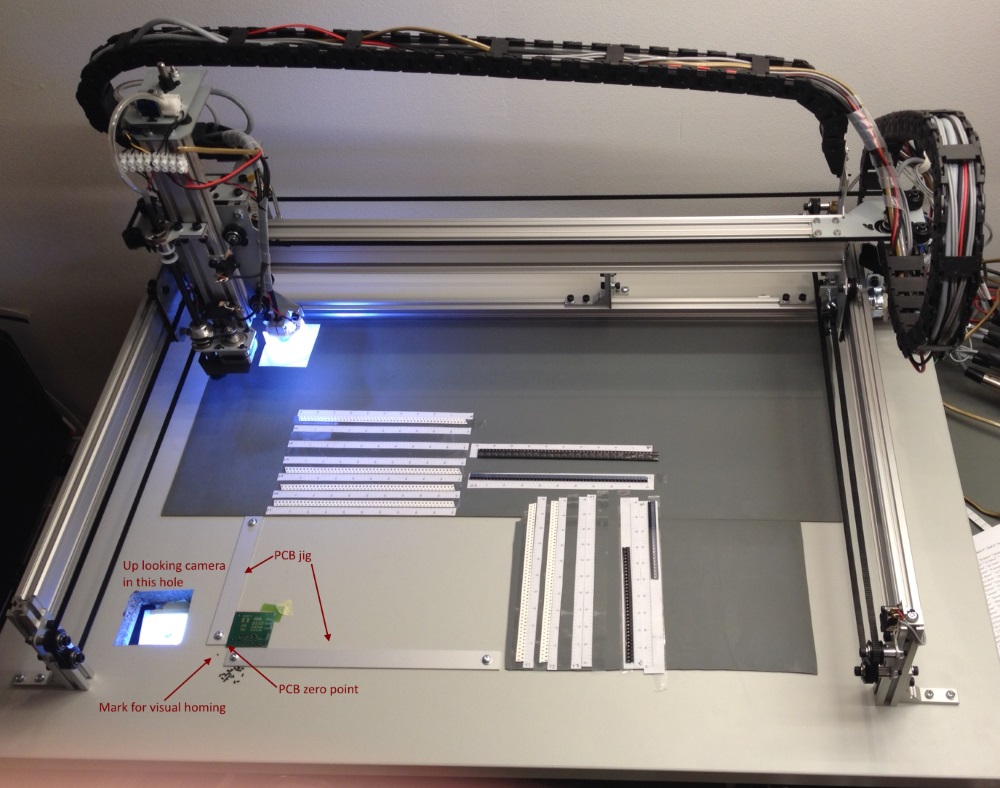
Take some time to think how you want to arrange the machine work area, such as where is the most convenient location of the PCB, how big PCBs you are most likely to build, where you want the free parts pick-area to be, where the most used components are going to be placed and so on. You want to minimize the machine movements (making it a bit faster) and you want to maximize your work ergonomics. Note, that only the area where the needle can reach and the down-looking camera can see, is usable for work. Figure out how much table room you are going to need in front and on sides of the machine.
The exception is the up-looking camera. The camera will be mounted under the table – we want the needle to be in focus at the PCB surface level. The best location for that is the left side of the machine, as only the needle needs to reach it, there is no need for the two cameras to see each other.
My table at one point of development is here. Please note that I don’t consider this by no means optimal! I present it just to show what you want to consider. I’ll tell about the reason for ESD mats on a ESD table on next page, selecting the table. 🙂
Once you have decided where the machine is going to be and where the up-looking camera location will be, make a hole in to your table(!). The size and shape of the hole is not critical, a round or square hole of 5 to 10 centimeters is fine. You can do the hole at a later stage as well, but if you have it done when you start, you don’t have to move a partially built machine.
