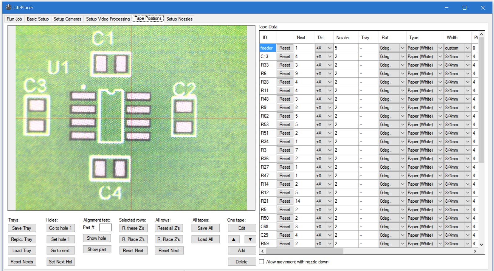
You set up component placement locations on the Tape setup page.To understand the rest of this page, please see discussion about tape orientations.
Main part of the page is taken by the tape data table on the right. The most relevant columns of the table are:
“ID”: The name for this tape. You can use any name you want; the important thing is to use a name that you can identify later.
“Reset”: Sets “next” column to 1.
“Next”: The number of the part used next. As defined, the tape parameters refer to part tapes with part numbers starting from 1. The tape can be partly used, so here you tell the software where to start picking. The program saves the table at closing, so tape usage is
“Dir” tells the machine which direction the part count increases; in other words, which way the tape is on the table. Please see this page for orientation illustrations.
“Nozzle”: Which nozzle is used for this tape.
“Tray”: See below the Trays section
“Rot”: Part rotation, this tells which way the components are placed on the tape pockets. A tape in +Y orientation with part rotation value of 0, means that components from that tape will be placed to the PCB “as is”: If a part is at 90 degrees on the CAD data, it is rotated 90 degrees counterclockwise (positive direction) when placed. The different tape orientations are automatically accounted for.
“Type”: Which algorithm is used for this tape.
“Width”: This dropdown column has the standard tape width and component pitch selections. The first number is the tape width, the second number is component pitch. Selecting a standard width automatically updates the pitch and offset values correctly.
The rest of the table is coordinates and parameters, that you set in the edit tape dialog.
Sections below the camera image box:
One Tape
Here you can “Edit” a tape. Select a cell in the table and click edit; the edit tape dialog opens. The arrows arrange the table. To add a tape, jog the machine to the first reference hole of a tape and click “Add”. The edit tape dialog opens. Also, you can open the dialog also on right clicking a cell in the table. To delete a tape definition, select a cell on the table and click “Delete”.
All tapes
“Save all” saves the content of the table to a file. “Load all” loads the table from a file. Note: The current content of the table is lost, unless you have saved it.
Selected
“Delete” removes tapes, that have a cell selected on the Tape Data table.
All rows
“Reset All Z’s” button sets pickup and placement Z values to undetermined, forcing the program to measure the values when the tape is used.
“R. Place Z’s” button resets the placement Z values only. You would use this when your tapes are set ok, but your PCB is thicker or thinner than normal, or you are populating the second side of a double side board and have the board elevated.
Selected rows:
Like “All rows”, but only for the selected rows on the table
Alignment test:
Here you can test that you have set the parameters correctly. Select a cell in the table for the tape you are testing. Then:
“Part #”: Put a part number in this box.
“Show hole” takes the camera above the hole that will be used to find this part.
“Show part” takes the camera above the part itself. A blue arrow shows the orientation of the part.
Holes:
Select a cell in the table on a tape row:
“Go to hole 1” takes the machine over the first hole.
“Set hole 1”: Sets the current machine position as the location of the first hole of the tape.
“Go to next” takes the machine over the hole that will be used to locate the part, that will be used next.
“Set Next Hole”: Sets the current machine position as the location of the next hole of the tape.
Trays:
The idea is that you can use trays of tapes (most likely, on holders) mounted on a carrier with alignment aids (so that they sit on the same location each time) and this way, replace several tapes together.
“Save Tray”: Select a cell in the table. Clicking this button will save those rows that have the same content in the “Tray” column to a file.
“Replc. Tray”: Select a cell in the table. Clicking this button will read a file with tape definitions and replace the rows that have the same content in the “Tray” column with the content of the file.
“Load Tray”: Adds rows to the table from a file.
“Reset Nexts”: Select a cell in the table. Clicking this button will set the “Next” column to 1 on all tapes, that have the same content in the “Tray” column. You use this when you have filled the whole tray with new tapes. If you have changed only some tapes, use the “Reset” button on the table.
