Find and remove the flanged bearings from the Y axle tube. (Not all bearings fit to all precision Y tubes, therefore they are supplied as matched set).
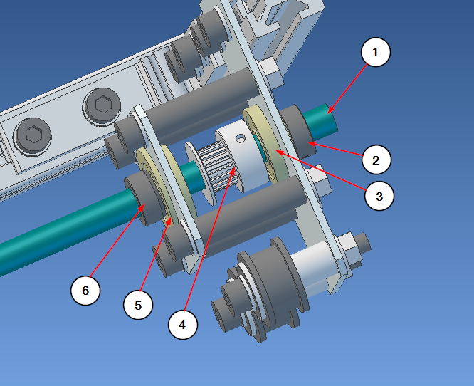
Mounting the Y axle starts from back left side. Start pushing the long tube (green for illustration) towards the motor and while doing that, put the parts on it in the indicated order. Please note, that the illustrations show the end result; when starting, the long end of the tube is on right side in the first picture.
On left back corner:
- Y axle tube
- SCCN8-x shaft collar, narrow side to the bearing (push tube from the thicker side)
- 608ZZ flanged bearing, flange outside the Y pulley subassembly
- GT2-20 pulley, 8mm bore; note the orientation
- 608ZZ flanged bearing, flange outside the Y pulley subassembly
- SCCN8-x shaft collar, narrow side towards the bearing
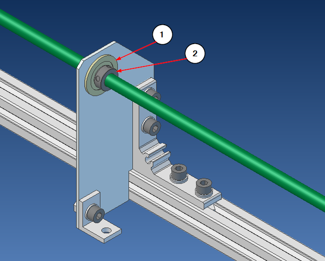
On the middle support plate:
- 608ZZ flanged bearing
- SCCN8-x shaft collar; narrow side towards the bearing
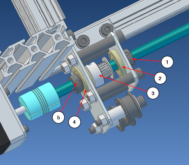
At the motor:
- SCCN8-x shaft collar, narrow side towards the bearing
- 608ZZ flanged bearing
- GT2-20 pulley, 8mm bore; note the orientation
- 608ZZ flanged bearing, flange outside the Y pulley subassembly
- SCCN8-x shaft collar; narrow side towards the bearing
Push the tube to the coupler, less than half-way through; you don’t what the motor and the tube ends to touch*. Ensure free rotation of the shaft. Tighten the shaft support structure roughly but not precisely midway between the two ends. Ensure free rotation again. Tighten the set screws on the coupler, and get a feel how easy it is to rotate now, when the motor is connected. Also tighten the set screws on shaft collars (they hold the bearings in place), but don’t tighten the pulley screws yet.
*: The idea of the coupler is that the middle portion inside the coupler is empty, so it can flex a little even if the motor and the shaft are not perfectly in line with each other (they are not). This way, there is no binding or extra resistance when turning.


