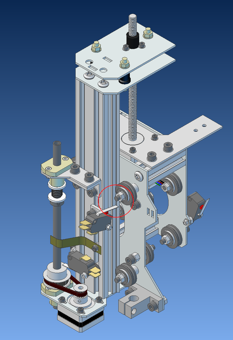
Adjust the upper limit switch so, that the lever hits the bolt end as shown in the image below. Make it so, that the switch activates before the bar reaches the upper limit of its travel. Here is what the finished gantry assembly should look like:
If you need to check a detail that is not visible, here is a zoomable and rotateable PDF of the gantry.
