Overview:
You have a possibility to select “Up Cam Assisted” method for component placement in the Run Job table, “Placement Method” column. This method works so, that before placing the component, the component is taken over the up looking camera and its position on the nozzle is measured using the vision algorithm specified in the “Placement Algorithm” column.
Note, that this method uses only “Nozzle Nominal Offset” and “Up Camera X&Y” numbers when calculating the component position. These parameters are on “Setup Video Processing” page. If you see any systematic errors in placement, first make sure that “Probe Down” commands in the lower right corner of the user interface work as intended. These take the nozzle down to the point shown in camera. When this works accurately, any remaining error is due to Up Camera coordinates: If you decrease the X coordinate, component placement moves to right (+X). If you decrease Y coordinate, component placement moves up (+Y).
Example of vision setup:
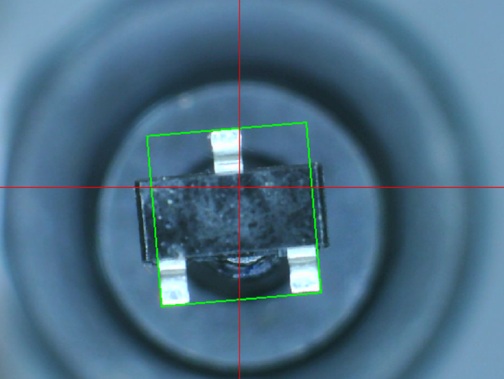
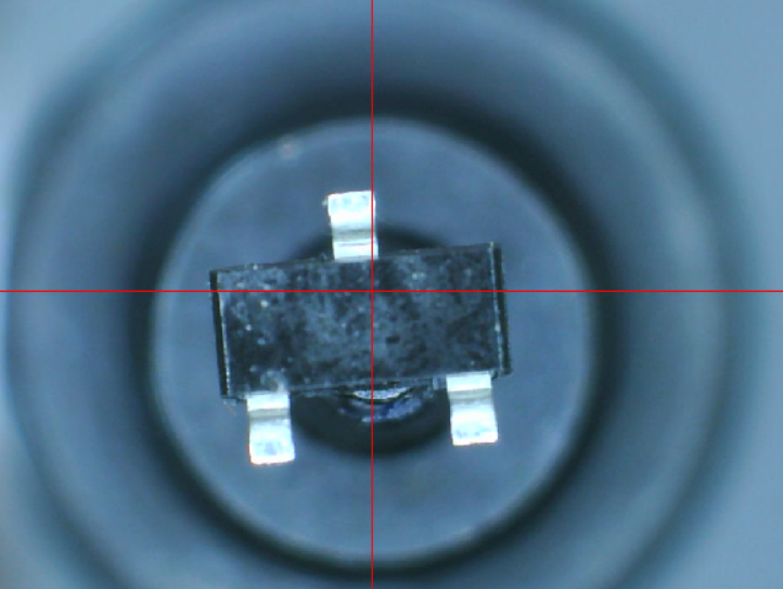
Here is an imperfectly picked up SOT-23 transistor (zoom x2).
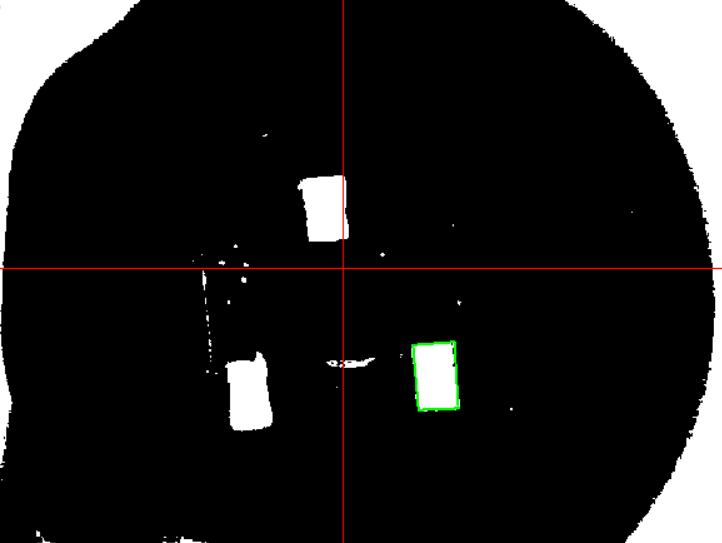
With threshold at 130, the leg “blobs” are cleanly separated. In this picture, I searched for rectangles and measured the size of one leg that was cleanly seen to be 0.42 x 0.68 mm.
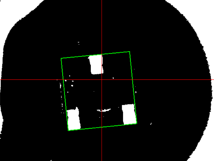
Then I used the “Filter Features by Size” function with min. size at 0.2, max. size at 1 and distance of 3 to focus on leg “blobs” only, and searched “Components by Pads”. This search function takes all solid white areas in the image after filtering to be a “pad”. A pad doesn’t need to be any particular shape. Then the function calculates a rectangle, that encloses all the “pads” (after filtering). This result is a “component”. This framed the part nicely.