This is a long page, but do read and go through all steps here.
Powering On and Off
When starting work, the correct sequence is first turning power on, then starting the software. at the end, close the software first, then power off TinyG.
First Power On
NOTE: During setup, the software will ask you “Home machine now?”. Do not click yes, until the homing operation is properly set up. After the homing is set up, always answer yes – the question means that the accurate physical location of the machine is not the location the software has.
Check your wiring once more. Before first power on, turn the Motor4 current trim all the way counter-clockwise (minimum position), then turn it up about 10%. Manually push the machine to center of your work area. Also, manually turn the Z axis down somewhat; we want to have room for check-up. Connect TinyG to a USB port on your machine and turn power on. You should see a blue light turn on and a red light blinking for a while, then some green lights and the red light constantly lit. Good. Then, start the LitePlacer control program, and select the Basic Setup tab.
On top left corner, there is a box labeled “Serial Port:”. If this is not automatically populated, press the “Refresh List” button. If you know which serial port is the TinyG, select that one, otherwise you have to try them on by one. Press “Connect”. With the right port connected, you should see some communication on the log window and values getting set in the boxes.
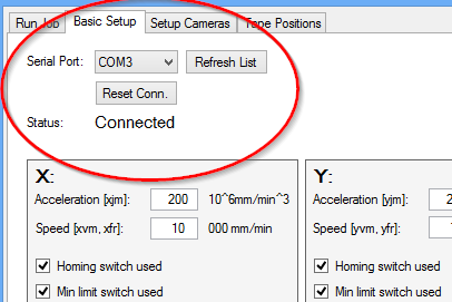
Congratulations! You have established connection to TinyG, and are now ready to set up the machine. If the values in boxes are not getting updated, there is no point continuing, you need to establish reliable connection first. See Communications troubleshooting section at the end of this page.
Setting Default values
Note the two “Reset to Defaults” buttons on top of the window. One is for application settings, one for control board settings. Click the one for control board settings. Again, you should see some communications and values changing.
Please note: The default values for speed and acceleration are rather conservative; you probably want to test and increase these. Note also, that the application settings already have their default settings. If you change them, they do retain their values if you update the software. If you want to start over, you can use the reset button for the application values.
Checking Motor Connections
Press Alt+F6. The machine should move 10mm to right. Press Alt+F7. The machine should move 10mm away from you. Press Alt+F12, and the Z axis should go 10mm down. Finally, press Alt+Shift+F9. The needle should turn 90 degrees counter-clockwise.
CAUTION: If you need to change the wiring, turn system power off first! Failing to do so WILL kill your TinyG!
If any of these does not happen, check your wiring. If any of the movements happen to opposite direction, turn power off and swap one of the motor pair wires.
Checking Limit Switches
If you don’t have an easy to activate switch wired to TinyG reset connection, now it is a good time to install one.
By default, limit switches are not enabled, because it would be hard to get this far if there would be a problem with their wiring. But now, enable one of “xxx limit switch used” tick boxes in Axes setup box, X tab:

If you have no problems in wiring of your switches, nothing should happen, and you should still be able to move the machine 10mm to right with Alt+F6. After activating a tick box, manually trip the switch. You should see blinking red light at TinyG and get a message from the control program. Press reset button and re-establish connection with TinyG*. Repeat with both limit switches in all X, Y and Z boxes (A axis has no homing switches). Assuming no issues at this point, enable the homing switch tick boxes as well.
Of course, if there were any issues, correct them before continuing. See the “Wiring the Limit Switches” page for wiring instructions.
( *: If a limit switch is triggered, it means that the machine is not where the software thinks it is. The job is ruined anyway, and continuing the effort would only increase the damage. Therefore, stopping the machine is the right thing to do. The TinyG designers decided that a panic state that you can only get out by a complete reset is the safest option. After all, TinyG is originally built for CNC machine control, and those machine usually have heavy toolheads with powerful motors with sharp bits attached to them.)
Test Homing
Next, press the “Home X” button on the “Mechanical Homing” group:

The machine should travel to left, hit the switch and back off a little. If it tries to go past the switch, press reset immediately. Be sure the “Homing switch used” tickbox is set and check the wiring once more. If the machine was unable to move, check your mechanics, also see that the trim potentiometer at TinyG Motor1 section is about midway or so.
We’ll get to manual machine movements later. For now, learn that Alt+Shift+F6 moves the machine 100mm to right. Do that, and re-test homing.
Repeat for Y and Z axis. For Y movement, Alt+Shift+F7 backs it away 100mm, for Z, Alt+F12 takes it down 10mm. Note, that Z axis home is at the up position and there is no homing function on the rotary (A) axis.
Note for Z homing Switch position
Now when you have your Z homing working, you also know the upper position of the Z axis. Manually insert a nozzle to the nozzle adapter. Ensure, that this position is high enough to allow movement over the nozzle holder rack.
Setup Homing Speeds
In the “X” box on the Basic Setup tab, there are adjustments for “Homing acceleration” and “Homing speed”. The former adjusts how fast homing reacts, the latter how fast homing cycle moves in steady state. When you adjust values, you notice that the numbers turn red. This indicates that the value on your screen is different from what TinyG has. Press enter to send the value to TinyG.
You want the homing movements to be smooth without any clunks or other effects. You also want the homing acceleration/decelaration be as fast as it can be while being smooth; do note, that acceleration values is also deceleration. If a limit switch triggers, you want to machine to stop as fast as it can. Besides, with (too) small deceleration value, you might not have enough physical room for the machine to stop.
You also want reasonable speed: You will be homing the machine regularly, and you don’t want to wait minutes each time. (For reference: At the time of writing, I have my machine homing acceleration/speed set at 4000/3000 for X, and Y, and 4000/1000 for Z).
Press the “Home XYZ” button and enjoy your work!
Note, that homing is not yet properly set up; we’ll get to vision processing homing setup later. For now, continue answering “No” to the “Home machine now?” question.
Jogging
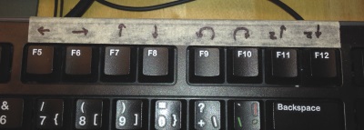
At lower right corner of the program there are remainders for the jogging controls: F5 moves left (-X), F6 moves right (+X), F7 moves away (+Y), F8 moves towards you (-Y), F9 turns counter-clockwise (+A), F10 turns clockwise (-A), F11 moves up (-Z) and F12 moves down (+Z).
Default movement is 0.1mm or 0.1 degrees. Shift is small multiplier: Shift+Fn key moves 1mm/deg. Control is for precise control, and Ctrl+Fn key moves 0.01mm/deg. This is too small movement to cause movement on one press, but cumulatively, a few of these will have an effect. Alt is a big multiplier. Alt+F key moves 10mm/deg. You can combine these: Alt+Shift+F key moves 100mm/90degrees, Alt+Ctrl+F key moves 4mm/deg.
Numpad arrow keys also move the machine in X-Y dimensions, but there is no precise control of the amount. Please note also, that when you move the machine in Y direction, the squareness correction is not applied. (We’ll come to this later; see “Setups Using the Cameras: Squareness“).
You might want to put remainders on your keyboard, like I did:
Setting up Movement
First, we’ll set the machine limits. Home the machine with the “Home XYZ” button. Then jog it to right a couple of cm’s short of tripping the limit switch. Note the X coordinate in the status area, and put this number to Max X machine size. Similarly, find the maximum Y movement of the machine and put this is the Max Y box. These affect to the X, Y test movement amount.
Actual Z travel will be determined in run time. The travel used in fine-tuning the Z movement is in the “Z test travel” box. However, the Z axis is not yet set up. Put some number to “Z0 to PCB” box in the Nozzle height calibration box, so the software doesn’t complain about “below PCB” travel attempt during testing.
Test buttons
“Test X” button moves the machine from X0 to Machine Size Max X. Next click will move the machine back to X0. “Test XY” moves form (0,0) to (MaxX, MaxY) and back, “”Test YX” moves along the other diagonal. “Test Z” moves Z axis down and back up. “Test A” turns the tube one revolution back and forth. Finally, “Test XYA” is like “Test XY”, but with added A axis revolution.
Adjusting currents
When adjusting the machine movement, you probably need to adjust the motor currents on TinyG. When doing so, be careful to not overturn them, they only have 270 degrees of movement. Also, be careful to not cause short on TinyG!
You want to adjust the current so, that you have enough current for all the movements, but not to unnecessarily heat the motors. The motors use maximum current when powered on but idle. Check them after some use; you don’t want the motors to be very hot to touch. The A axis should not need hardly any force to turn, so a low setting there is good.
WARNING: High current setting on A is too much for the small motor!
For reference, I ended up with these motor current settings, for no particular reason: x: 100%; y: 90%, z: 60%; a: 30%.
When finding the speed limits of your machine, you will stall the motors. That is easy to notice: the motor will emit a strange sound and the machine does not move as expected. Do not click the test button again, as the software has lost the machine position and would crash the machine. Instead, home the relevant axis.
Adjusting movement
The movement controls are the Acceleration and Speed on top of the motor control boxes. As implied, acceleration controls the start and stop phases of movement, speed the steady-state phase. Using the test buttons, adjust the machine for smooth movement. Look for signs of “unsmoothness”, such as noise, vibrations etc. Of course, you don’t want the machine to stall. Make sure to check X movement with various positions of Y and vice versa.
Note, that you want maximum smoothness, not maximum speed. You can always come back here for re-adjustments, should you find that necessary. Note also, that the motors will stall somewhat easier when they are hot: If you set the machine as fast as you can, the movement might fail in a long placement job. So, be conservative, at least at the beginning.
For reference, the settings I have at the time of writing are close to the fastest that my machine can move smoothly: Acceleration/Speed are 3000/15 for X, 4000/20 for Y and 12000/6000 for Z. There is no point in finding maximum values for A, as the rotation will happen mostly during X,Y moves, so used speeds will be slow anyway. Besides, you don’t want the parts to turn on the nozzle because of inertia and fast moves.
Other settings on the Basic Setup page
Vacuum
Now is a good moment to check that “Pump On” checkbox activates and deactivates the vacuum pump and the “Vacuum On” checkbox activates the vacuum on and off at the nozzle tip.
Motor Power
Even when not moving, the motors are normally energized, as the machine actively holds position. The downside is that the stepper motors heat up the most when not moving. Therefore, it is not a good idea to keep them on indefinitely.On the other hand, the motors loose precise location when powered off due to magnetic backslash. To solve the dilemma, there is a built-in timeout in the TinyG for this. The software is aware of the timer and will prompt you when it times out. You can control the motor power also manually using the “Motor Power” checkbox.
Slack Compensation, Small Movements and Miscellaneous Settings
All mechanical systems have some backslash or slack, however small. Also, microstepping stepper motors have some between the steps. For most accuracy, the machine can be set so, that all positions are approached from same direction with same speed, minimizing the slack effects (the slack is always on the same side of the motors and axes). Unchecking the “Slack Compensation” makes for a bit faster and smoother machine at the cost of accuracy. You’ll find out if you need to use this when doing test runs.
The “Small moves speed” setting controls the speed of slack compensation and other minor moves. This affects the smoothness of the slack function and some camera based calibration location searches.
Setting the squareness correction requires the downlooking camera to be correctly set up. We’ll cover this later.
The vacuum time settings are self-explanatory. You’ll notice if there is a need to tune these.
You can find the full description of the Basic Setup Page in the Sofware Reference. The relevant page is here.
Troubleshooting
A axis rotation issue
The A axis mode sometimes resets itself. (Fortunately, rarely, and almost never twice on a same system. If you find out why, please let me know.) When this happens, the A axis rotation movements become very long. To fix, type $aam=1 to the “text to send” window and press enter.
Communications Troubleshooting:
The connection needs the virtual serial port driver from FTDI. Your system might not have it. If not, it may seem that the software connects but nothing happens. A customer reported: “When connecting the device, it seemed like it connected but nothing would happen. I installed the recommended FTDI driver, and when I connected, it added a ‘usb serial converter’ device under univeral serial bus controllers. right click on that, go to properties, advanced, and select load vcp. then unplug and replug it in — the serial port is then added after this is enabled.”
The driver is available here.
If the board seems unresponsive, unconnect switch and reset connections. To rule out USB issues, unplug other USB devices (hubs, cameras etc) from your system and connect TinyG directly to a computer USB port.
If you get some communication, it is possible that the communication parameters are set incorrectly. I have seen this a few times, but so far, I have no idea why that should happen. Fortunately, it is easy to correct:
Type {“sys”:””} in the “text to send” window and press enter. You should see this:
{"sys":""}

 {"r":{"sys":{"fb":438.02,"fv":0.970,"hp":1,"hv":8,"id":"1H4973-HTS","ja":100000,"ct":0.0100,"sl":0,"st":0,"mt":300.00,"ej":1,"jv":3,"js":1,"tv":1,"qv":2,"sv":1,"si":200,"ec":0,"ee":0,"ex":1,"baud":5,"net":0,"gpl":0,"gun":1,"gco":1,"gpa":2,"gdi":0}},"f":[1,0,11,2816]}

 ReadyEvent sys group
Here is an example of erroneous sys report:
{"sys":""}
{r:{sys:{fb:438.02,fv:0.970,hp:1,hv:8,id:”3W5230-MEV”,ja:0,ct:0.0000,sl:0,st:0,mt:300.00,ej:1,jv:3,js:0,tv:1,qv:2,sv:1,si:100,ec:1,ee:0,ex:1,baud:5,net:0,gpl:0,gun:1,gco:0,gpa:0,gdi:0}},f:[1,0,11,7411]}
There are missing quotes, extra spaces and a missing event report, but most importantly, some of the parameters are different. The “e_” and “j_” parameters are the important ones. To correct these, type these commands to the “text to send” window and press enter:
$js=1

$ec=0
You might need to set others too, but unlikely. Note, that some of these are read-only and not supposed to change.
Previous (Overview of User Interface)