Please note, that the limit switches should be operational at this point, before going further!
The nozzle has a switch that activates when the nozzle goes down far enough. This is used to measure component pickup and placement heights, greatly saving time in setup. This probing action needs to be calibrated.
Now is an excellent moment to re-check the tube movement: I recommend that for setup, you loosen the springs and use the weight of the tube as a starting point. When you push the tube up from the nozzle tip, these should happen, in this order: The tube goes up, triggering the switch. Then, the bottom collar goes up against the lower bearing. Only after this, would the spring in the nozzle adapter start to compress. When you let go, the tube should drop fully down under its own weight, at all rotational positions. If this is not the case, fix it now, since this step will mask the error, which is later hard to diagnose.
If you haven’t done so yet, attach a nozzle to the pickup tube. If you triggered the switch, press reset on the TinyG and after the message, click “Clear error” and “Connect” to re-establish connection.
The Nozzle height calibration section is this:
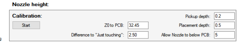
Click “Start” and follow the instructions: First, place a regular height PCB under the nozzle; you can jog the machine to a suitable position for this. Clicking next will take the nozzle down until the switch triggers, then backing up a little to clear the switch. This is “full down”. You are asked to jog the nozzle up until it just touches the PCB surface. Pressing F11 will take the nozzle up 0.1mm at a time, Shift+F11 is 1mm up. Click next to finish.
The results are:
“Z0 to PCB”: The “just touching” distance from Z0 (full up) to the surface of regular PCB. This parameter is mostly used with up camera measurements. In regular use, the component placement z values depend on component heights and are measured.
“Difference to Just touching”: This is the difference from “full down” to nozzle tip just touching, not pressing down on the target. To avoid false triggers during use, aim for at least a mm or two. This is controlled by the physical mounting of the switch.
The parameters you set:
“Pickup depth”: When picking up parts, this is the amount of additional Z travel from “just touching”. In most cases, pickup doesn’t require much.
“Placement depth”: When placing parts, this is the amount of additional Z travel from “just touching”. You set this to be enough for the parts to stick to the solder paste (with most pastes, not much, maybe even negative, since the paste is already up from the PCB). You should have some clearance left to “full down”. For example, with the values above, I have 2mm safety distance (plus the switch hysteresis) for avoiding unintended switch triggers when using the machine.
“Allow Nozzle to below PCB”: To guard against wrong measurement results, bad setup and user errors, the software asks for confirmation if any operation seems to go deeper than normal use requires. Here you can set the allowance for that. With my numbers shown above, I’ll get a notice if something tries to get the nozzle more than 37.45mm down.