UPDATE:
The blog post on this page is outdated. I now have 4k cameras, that are faster and of course, more accurate. The mount is re-designed so, that after adjusting, you can tight screws and lock it in place. Links to the design files are in this forum post.
Original blog:
Some time ago, I decided to change the cameras used with LitePlacer, as the manufacturing quality of the old type got progressively worse. So, first I started to look for the camera itself.
Selecting the camera
I had a few criteria for the camera. It needs to have a good image quality, preferably in HD. Also, the form factor should be such, that it is possible to design an adjustable mount (more of that below): Making the camera to look exactly down eliminates some errors and make variations in height less of an importance. It must be able to focus close. Price is a factor, but not the main one.
I looked to some manufactures, eBay and AliExpress. I bought 20+ samples of various types. Some were in unattractive form factor, such as camera used in laptops, very long strip. Some were very hard to focus. Some had horrible lens distortion when focused close. At the end, I selected the HBV-1517 module from Huiber:
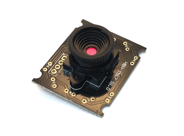
The form factor is nice. The focus needs adjustment and is not the most convenient, but it is ok; especially as in this application, it needs adjusting only once. The lens is deep in the focus ring, so it is easy to handle, without getting fingerprints on the lens. The image quality is great, with minimal lens distortion. Peculiarly, their one off sample price at AliExpress is less than quantity orders, but still, the sub-10$ price is nice. It is not particularly fast in high resolution (7.5fps at 1280*1024, 30fps at 800*600), but that is not the main speed factor anyway.
Designing the mount
Then, I designed the adjustable mount. For this application, the mount does not need to be fully adjustable; it is fine if the left-right tilt, front-back tilt and rotation adjustments are all just trims with sufficient range. Still, three way adjustment is not trivial. So, I’m writing this hoping that my design can inspire other people in their projects.
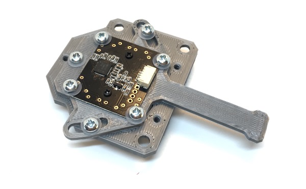
First, I came up with a camera holder:
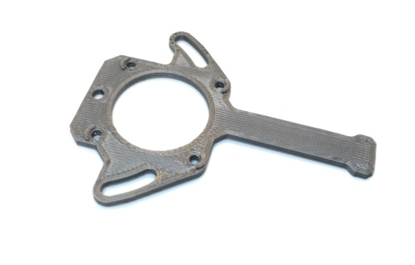
The long lever is the rotation adjustment and the place where the USB cable will be attached to form a strain relief. Note the small ridges around the four small holes around the round opening.
The camera module is screwed to this, using nylon washers to press the module down:
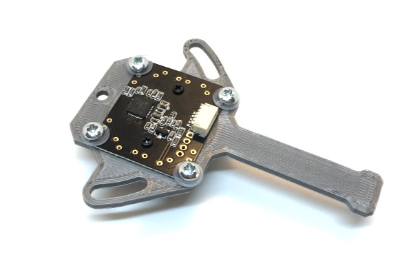
I used self-taping screws, Element14 part 2474936. Using self-tapping screws on 3D-printed parts is handy in assembly, but rather picky in design: The hole size needs to be exactly right for the screw to make a thread and get a good grip, but not break the part, especially in small sizes. Fortunately prototyping with 3D printer is easy.
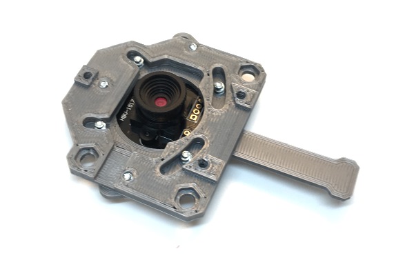
Then comes a part to hold these:
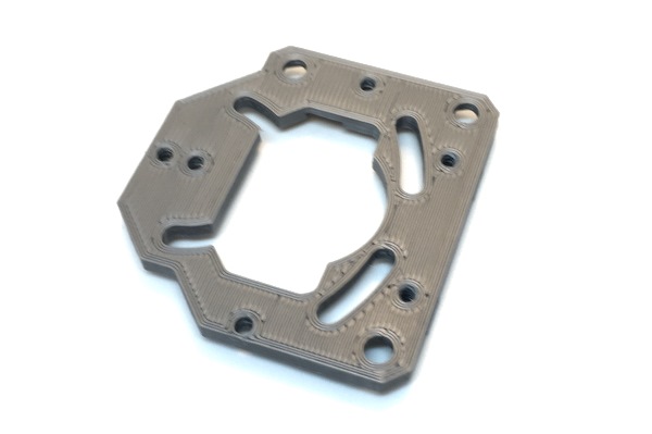
The cat-looking opening is for the camera, and the “ears” and “whiskers” of the cat are where the camera module screw ends go, allowing the left-right trimming. The parts are screwed together; the assembly turns around the screws on the back, and the screws on the side hold the assembly together. These will be tightened once the user is happy with the rotation adjustment.
Turn this around:
And install a LED ring light, again using washers to hold it in place:
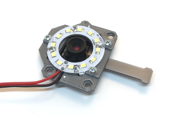
Note the hex shaped retractions. Finally, we need yet another part to attach this to the machine itself. Here is the actual mount, upside down, with three screws installed. Also, the screws have springs put on them:
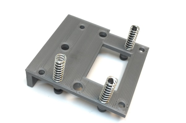
Then, the whole thing is put together: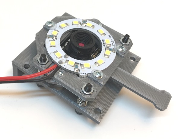
The camera module has now a three point straight angle mount. The closest screw is the base, that is not adjusted. The screw at upper right adjusts the left-right skew of the camera angle, without affecting the front-back adjustment. The front-back angle is adjusted with the screw close to the LED wires outlet.
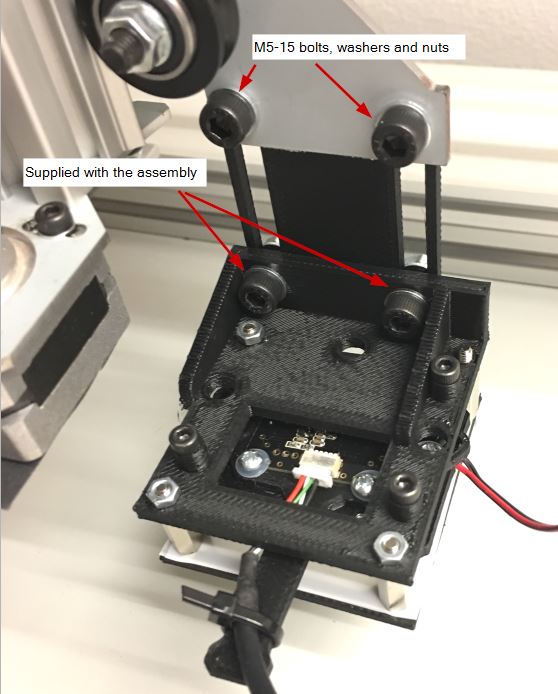
Here is the whole thing mounted on the machine. You can see a slotted plate that allows for height adjustment and a light diffuser assembly below the camera module assembly. The latter is just a rectangular holder for light diffusing films, mounted with standoffs to the corners of the camera assembly (image is taken from the assembly instructions).
The up camera assembly follows the same principles, but naturally, is not the same – but you get the idea!
Open source
My STLs are unlikely to be of use for you. As noted, the screw hole size is tricky, and depends on the printer, its setup, the filament and printing temperature. Most likely, the hole size I use is not suitable for your printer. Besides, you want to adapt the design for your machine and your camera module anyway. But here they are anyway:
Up looking camera STLs (not show in this post)
Down looking camera STLs (the subject of this post)
Much more likely to be useful are the 3D CAD designs. These are made using Fusion 360:
Down looking camera CAD design
Comments (please!)
I very much appreciate feedback and comments, especially if you find this post useful (After all, that is why I wrote this!). Please add your comments to my forum thread. If you prefer not to sign up but still want to share, email to me (juha at liteplacer.com) with permission to add to the forum is fine, too. Also, there is a thread at OpenPnP forum, too.