When you click “Measure” on the “Setup Video Processing” page, the software captures a frame from the video stream, applies the selected video algorithm to the image and shows the result on the log window. To diagnose issues and to be able to tune your algorithms, you want to be able to read the result. Here is how.
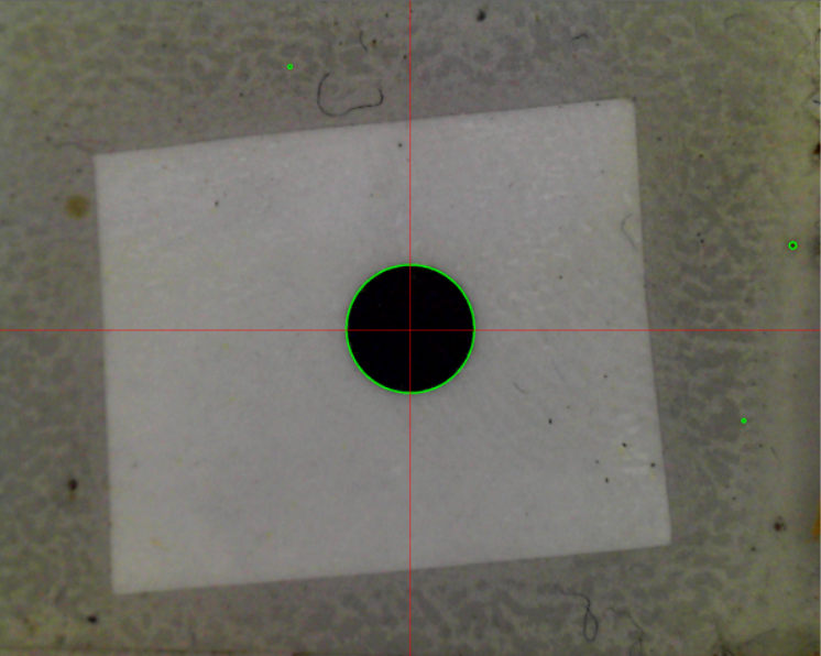
The target that I measured was this, shown using “show results” option. The true result is the big circle in the center, the unwanted items are the small speckles, also highlighted in green:
After clicking “measure” the log window showed this:
B: Measure
BuildFunctionsList:
Invert, 0, 0, 0, 0, 00, 0, 0
Threshold, 200, 0, 0, 0, 00, 0, 0
Result candidates:
Circles:
p: -187.0, 409.5px; -3.179, 6.962mm; s: 4.5, 4.5px; 0.08, 0.08mm; A: 0.00
p: 596.0, 132.0px; 10.132, 2.244mm; s: 10.0, 10.0px; 0.17, 0.17mm; A: 0.00
p: 0.5, 1.0px; 0.009, 0.017mm; s: 199.5, 199.5px; 3.39, 3.39mm; A: 0.00
Filtered for size, results:
p: 0.5, 1.0px; 0.009, 0.017mm; s: 199.5, 199.5px; 3.39, 3.39mm; A: 0.00
Filtered for distance, results:
p: 0.5, 1.0px; 0.009, 0.017mm; s: 199.5, 199.5px; 3.39, 3.39mm; A: 0.00
Result: X= 0.009, Y= 0.017, A= 0.00
Elapsed time 87ms
First couple of lines are debug information, showing the button I clicked and the processing functions list with parameter values that was passed to the measurement section. The results printed are listed for each feature that the algorithm is set to search for. In this case, only round features are targeted, so only one category is listed. There is a list of result candidates, each on its own line.
First the position (p) is shown. The values are x and y in pixels, then x and y in mm’s. Then there is the size (s); again first for x and y in pixels, then x and y in mm’s. Finally, there is the rotation (A) value. For circles, rotation is meaningless, so 0 is shown.
Looking closely, you notice that first two are tiny; these represent the noisy pixels in the image. The third result is large, and is what we are looking for.
As noted, the results are filtered for size. An accepted result needs to be bigger than minimum size and smaller that the set maximum size. After the size filtering, the remaining result candidates are listed. In this case, only one result candidate is left.
Then, a similar filtering is done for distance. Candidates further away than the distance set in “Discard distance” boxes, are thrown away. The remaining candidates are listed. Finally, the end result is shown, in mm’s (second to last line in the above listing). The result needs to be unique. If you have more than one possible result, the listing would show an error message.
The processing shows the effect of size and distance filtering in colors: Red results (for example, circles) are wrong size and discarded. Yellow results are right size, but more than “Discard distance” away from the image center. Green result(s) pass all tests. You should have only one green item.
Some functions use rather much processor time. The used measurement time is shown, so you can get an idea how much effect it might have in real use.
(The results here don’t quite match the image, as different frame was captured than actually measured.)