On this page, you set up the video processing algorithms:
Terminology: An algorithm is a collection of individual video processing functions together with information which features to search for and which results are acceptable. A function is a single video processing function, that may have its own parameters.
On right side, you can select which camera view to have in the picture box.
You can also Save and Load all the algorithms to a file. For now, the file name is shown in the log window. It is on the todo list to have a file selection capability.
The Current Video Algorithm drop-down box selects which algorithm is currently loaded for editing.
You can Add, Remove, Duplicate or Rename algorithms.
The No video processing/Show processing/Show results selection affects to the displayed image. The “Show processing” selection shows the same image that the features recognition stage sees. “Show results” highlights the found features over an unprocessed image.
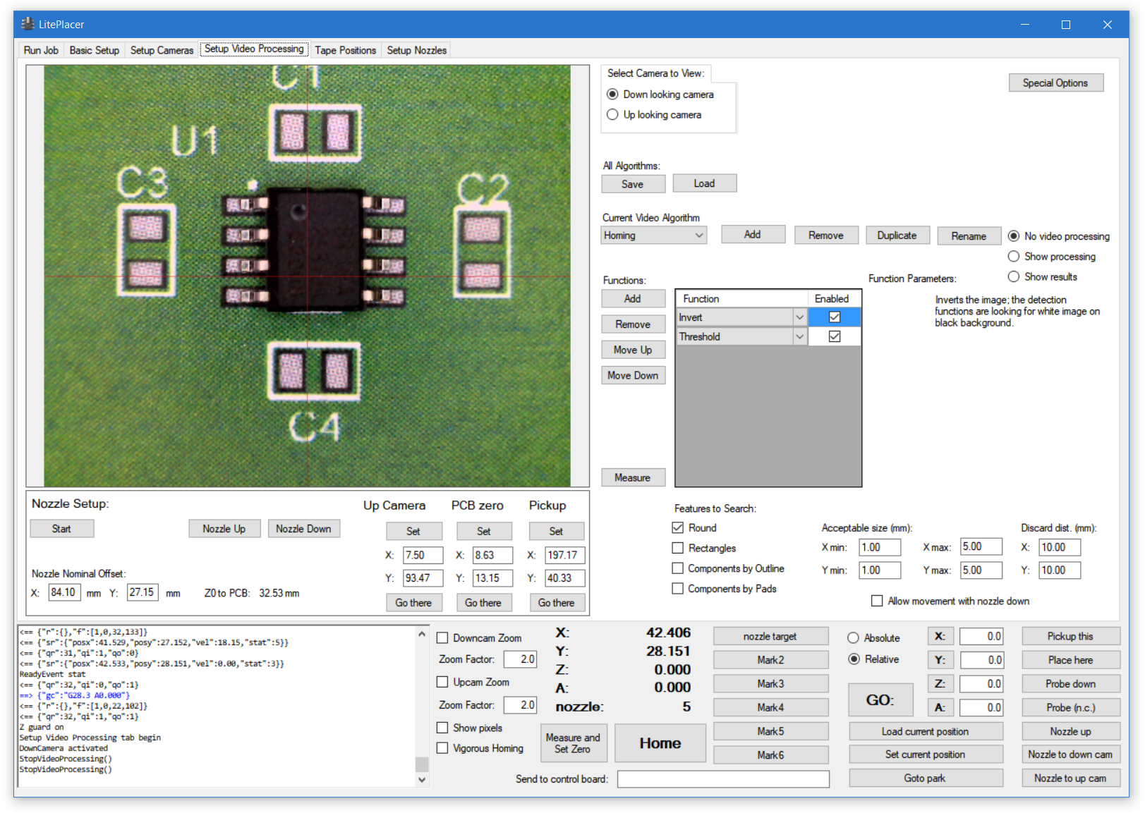
On the “Functions” section, you select which functions are used on the image. Here is a simple example:
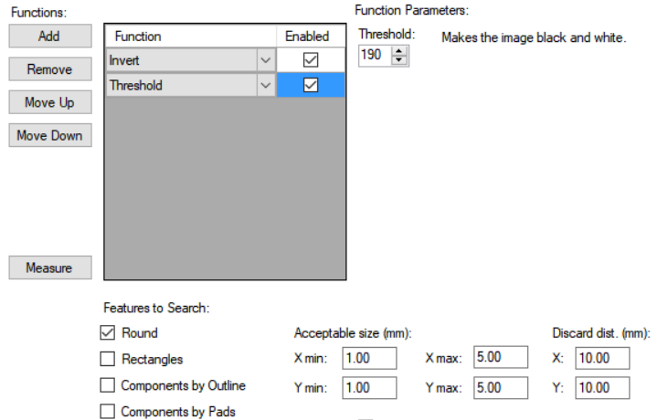
On the left, there are buttons to add and remove functions as well as arranging the list. Processing happens from up to down. Selecting a function brings a short explanation to the right, and makes function parameters (if any) visible.
“Features to Search” tells the recognition section what to look for. The section looks for white features on a black background. Therefore, most algorithms use the “Threshold” function. Pixels with brightness lower than the parameter value are converted to black, others come out white.
To filter out unwanted results, you set the “Acceptable size” for the result you want. When you edit the X value, the Y value changes as well – in most cases, you don’t need separate filtering for X and Y size. If you do, put the X value in first, then edit the Y value. Also, result candidates that are further away from the initial location than “Discard distance”, are discarded.
The “Measure” button runs the measurement routine on the image and displays the results on the log window. A deeper explanation is on this page.
For a simple example of how to use the video functions chain, please see this page.
For discussion about finding components, please see this page.
Available video processing functions are listed here, with explanations.
Below the image box are several functions, that don’t actually control video processing, but you need the camera image to set up:
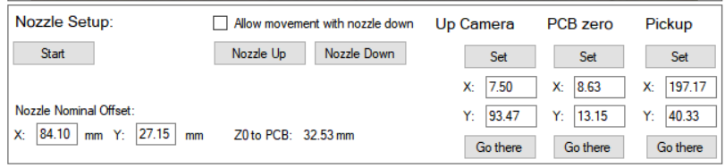
For “Nozzle Setup” function, please see this page. The “Allow movement with nozzle down” box does what it says, it disables this safety feature. You need this during nozzle setup.
Then, there are a few special locations. The Up Camera location is set in during the nozzle setup function.
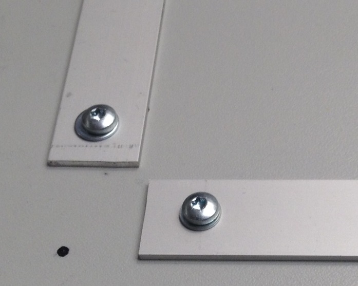
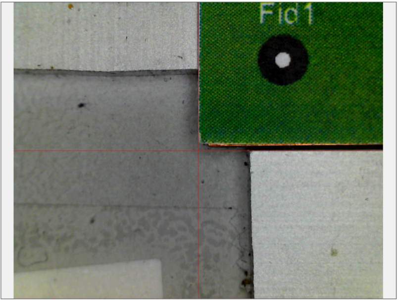
You should have a jig of some sort for your PCB. This way, when you place your PCB on the work table on the jig, the system can have a good enough initial guess of the location of the components, most importantly the location reference marks (fiducials). The system assumes PCB origin to be on the low left corner of the physical PCB, so the jig should define this. The jig corner location is the PCB zero position. Here is what I have (although I have now a better homing mark) and what the camera sees when the machine is there:
The system has a loose component pickup function. When this function is used, the machine tries to find the part from the “Pickup” position.
On each of these special locations, the “Set” button copies the current machine location to the boxes. You can input the locations directly to the boxes, too. The “Go there” button takes the machine to that location.