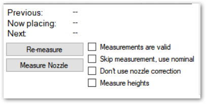
Below the camera image box, at center, are some miscellaneous items for placement:

“Previous”, “Now Placing” and “Next” labels indicate the row that the program is operating on.
“Re-measure” button re-runs the board measurement operation. Please see this page for details.
“Measure nozzle” button recalibrates the current nozzle
“Measurements are valid” checkbox indicate the status of the board measurement; you can also uncheck it to force re-measurement on the next operation.
“Skip measurement” checkbox makes the software to skip board measurements. Components are placed to their nominal coordinates using PCB zero location as the origin (see this page, at discussion about a jig, close to bottom). For example, if a components nominal (CAD data) coordinate is x:10, y:20 and your PCB zero location is x:5, y:8, the part will be placed to x:15, Y:28 without measurements.
“Don’t use nozzle correction” ignores nozzle calibration data. In some cases this might improve accuracy, when the nozzle runout is smaller than the nozzle calibration process uncertainty.
“Measure heights” checkbox makes the placement to ignore any placement z values in the tapes, forcing measurement of the z values during the placement. You would use this when placing the second side of a two sided assembly, when you have elevated the board from the table slightly, for example.
back to Software reference top page