On the “Setup Nozzles” page, you set up the automatic nozzle change. This page is the reference; for setup instructions, please see here.
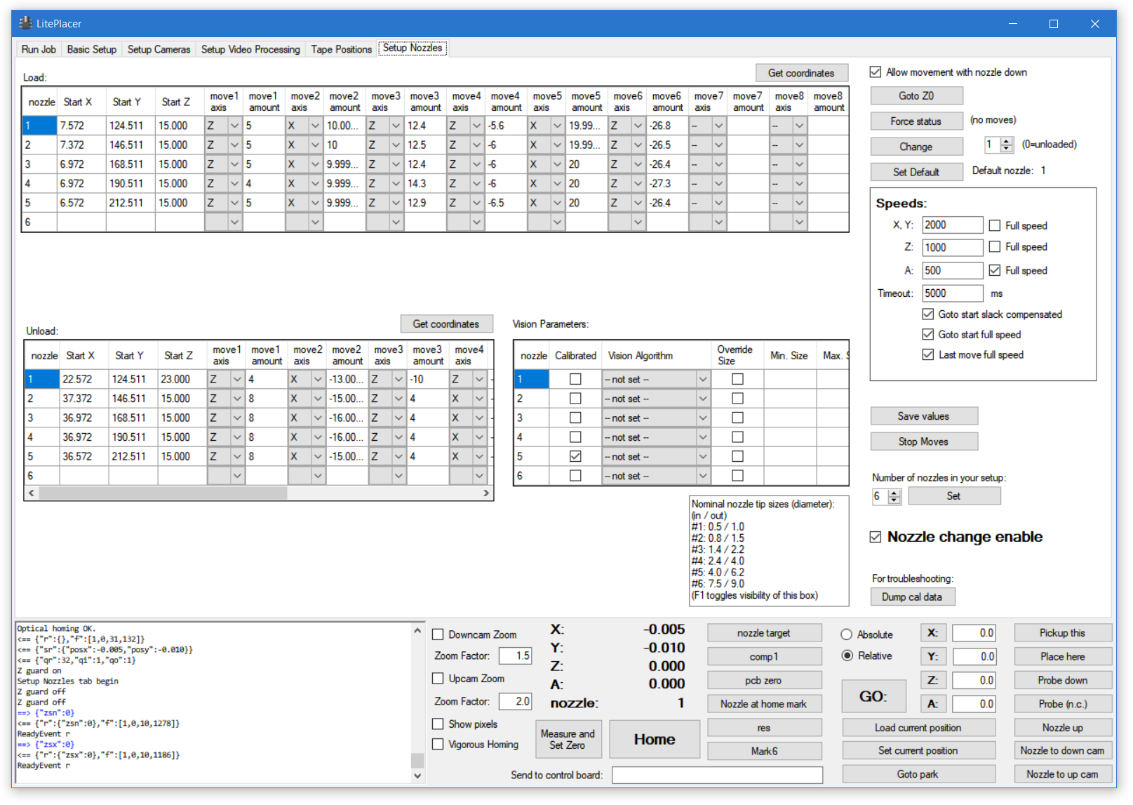
There are three tables: “Load:” table holds the load moves; “Unload:” table holds the unload moves, and “Vision Parameters” table, that has the nozzle runout (wobble) calibration parameters.
“Load” and “Unload” tables
When loading or unloading a nozzle , the program first goes to Start X, Start Y, Start Z position and then executes the moves in the table in order. For example, in the above picture, loading nozzle 1 would first go to start position, then lower the nozzle (Z axis) by 5mm, then move X axis 10mm to right (positive direction) and so on.
The “Get coordinates” buttons on the load tables are used in the setup. Assuming only one coordinate has changed from previous move, clicking the button automatically fills the value and axis and moves focus to next move column.
“Vision Parameters” table
Vision parameters table hold the information that is needed for optical runout (wobble) calibration. For each nozzle, the “Calibrated” checkbox indicates if the system has valid calibration data for this nozzle. “Vision algorithm” drop-down box allows to select the vision processing algorithm used to calibrate this nozzle. “Override size” checkbox determines, if the size information embedded on the algorithm is used or if the algorithm in this table is used instead. The “Min. size” and “Max size” columns hold the size information that the vision algorithm uses, if “Override size” is checked.
you can set your vision algorithms to target either the outside or inside of the nozzle tip. The reference box lists the diameters of the standard nozzles supplied with the LitePlacer kit. If your system uses non-standard nozzles you can hide the reference box by pressing F2.
Right side items
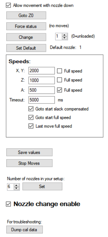 “Allow movement with nozzle down” disables the regular movement guard. Leave checked.
“Goto Z0” lifts the head full up. This needed often during setup.
“Force status” sets the status of the software to reflect what nozzle is actually loaded. Forcing the status does not perform any moves.
The “Change” button changes the nozzle to the one indicated in the number box, by performing the moves in the movement tables. Currently loaded nozzle, if any, is unloaded first.
“Set Default” button sets the nozzle that the system uses if no nozzle is specified for an operation.
If things go wrong, “Stop Moves” does what it says.
In the “Speeds:” box, you can set the speeds that the moves are done or opt to use the full speed specified on the Basic Setup page. The “Timeout” box sets a value for nozzle moves timeout. If you use very slow speeds, you might want to set a large number here. It is recommended, that in the start position and the position before last move in load/unload sequences are such, that the nozzle holder doesn’t touch anything. If so, you can use slack correction (if you have it enabled) when moving to start position, going to start position with full speed (recommended, as the head might be far away when a nozzle change is needed!), as well as doing the last move with full speed.
“Save values” button saves the load and vision tables data and the calibration values.
“Stop Moves” does what it says. During setup, do keep your speeds slow enough that you have time to click this if things go wrong.
The “Number of nozzles” selection controls the size of the tables. Set according to your hardware.
The bold “Nozzle change enable” checkbox controls if nozzle change is allowed in the first place. Check the box when you have completed the setup.
For troubleshooting, you can print the calibration data to the log window by “Dump cal data” button.