Please read the description of the nozzle setup page here. For repeatable results, I recommend using a reference for rotation zero. There is no homing on rotation axis, but make a mark on the big pulley so that you can see the axis position. Make it a habit to look at the pulley before powering on the machine, and if the mark is not pointing to your zero location, turn the axis by hand. You don’t need to be super accurate on this. I have a line on the pulley (not on the surface that the switch rests against) that points to me when the axis is at nominal zero.
Please open the “Setup Nozzles” page. Here, you set up the automatic nozzle change:
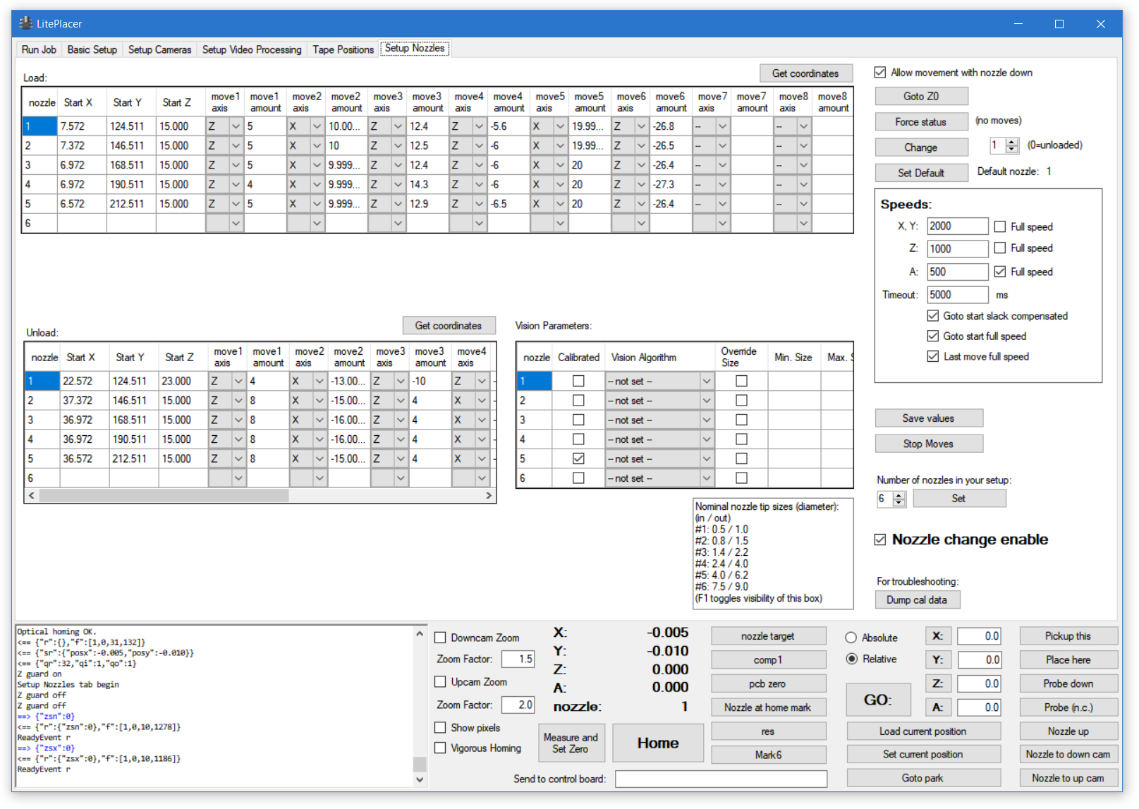
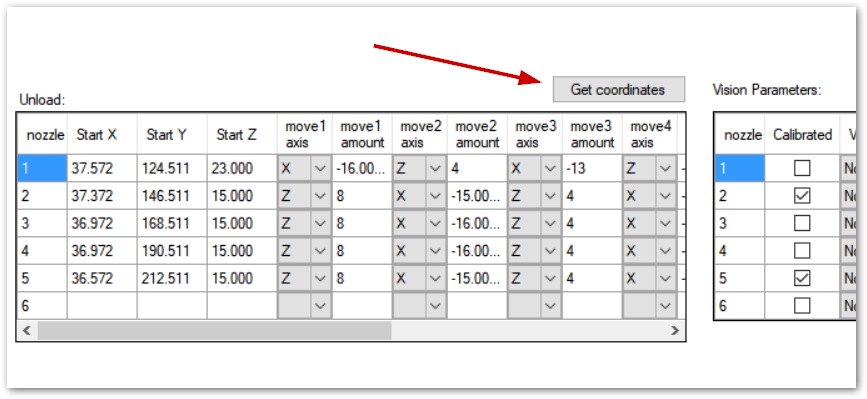
There are three tables (yours will be empty at this point): “Load:” table, that holds the load moves; “Unload:” table, that holds the unload moves, and “Vision Parameters:” table, that has the nozzle runout (wobble) calibration parameters. When loading a nozzle , the program first goes to Start X, Start Y, Start Z position, and then executes the moves in the table in order. For example, in the above picture, loading nozzle 1 would first go to start position, then lower the nozzle (Z axis) by 5mm, then move X axis 10mm to right (positive direction) and so on. OF course, for unloading a nozzle, the lower table is used.
First, let’s setup the parameters for the setup:
-Check the “Allow movement with nozzle down” box on top right. This turns off the Z movement guard.
-Remove any nozzles from the adapter and place the nozzles on the holder. Set the number box by the “Change” button to 0 and click “Force status”. This button does not cause any moves, it only changes the program status to be the same as the reality.
-On the “Speeds:” box, uncheck the “Full speed” boxes for X,Y and Z. Set a low speed on these, such as 500. You can set a faster speed when the moves are properly set up.
Nozzle 1 load moves
Then, we’ll set up the actual moves. Here, I’ll describe setting up the sequence I use. My holder is set so, that the long side is along the Y axis and taking a nozzle out of the holder (to right in the images below) is to +X direction. If yours is mounted differently, adapt the description below as needed. Of course, you don’t have to use my sequence either, although it might be a good way to gain understanding of the automatic nozzle load/unload function.
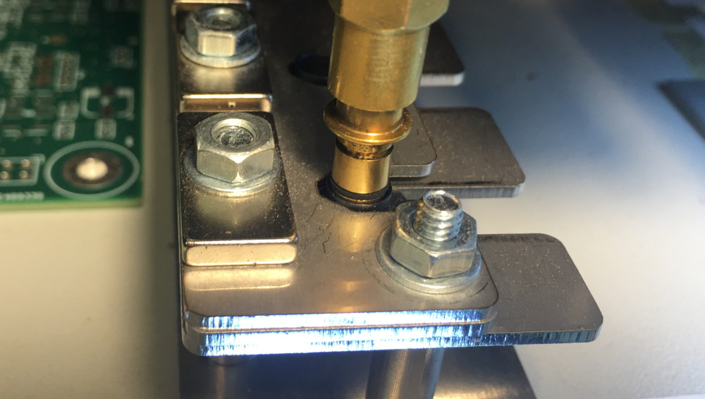
First, take the nozzle adapter over the first nozzle. Lower the adapter towards the nozzle in small steps, moving it in X, Y as necessary, until it is just entering to the nozzle. Try to be precise:
As a remainder: F5 moves to left, F6 to right, F7 towards the back, F8 to front, F11 is up, F12 is down. Plain key moves are 0.1mm, with shift they are 1mm.
Look at the bottom section to see how high your nozzle is. Write a number that is somewhat smaller to the” Z:” box in the bottom section (to right of the big “GO:” button). I used 15.0. Check the “Absolute” button and click the small Z button. This causes the nozzle to move to absolute coordinate, in my case to 15.0. The nozzle adapter is now at a good start position:

Click the number 1 in the “nozzle” column on the “Load:” table, and click “Get coordinates” at the up right corner of the table. The current coordinates of the machine is put to the Start X, Y and Z cells.
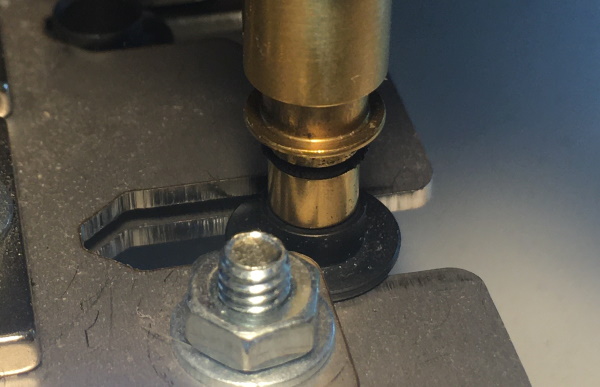
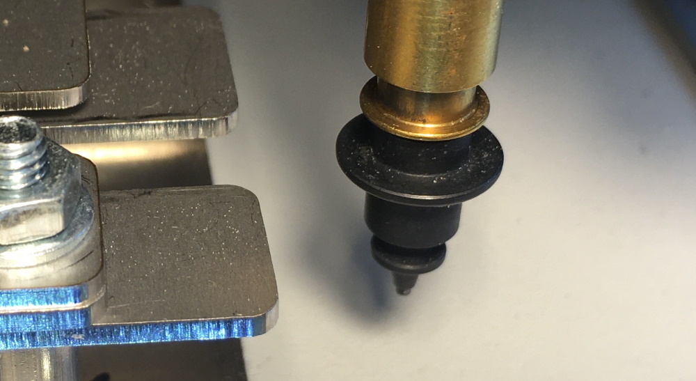
Take the nozzle down so, that the first o-ring goes in or is close to:
Click “Get coordinates”. The only axis that changes was Z, so the “move1 axis” is set to be Z and the move amount is automatically placed to “move1 amount” cell. We now take the nozzle out of its holder position; we don’t want to press the nozzle against the holder position when inserting the nozzle. The easiest way is to press Alt+F6, moving the nozzle 10mm to right:
Again, click “Get coordinates”.
Move the adapter in so that the nozzle gets fully inserted. First, the tube goes up, and the collar at the end of the tube presses against the bearing. Then the spring in the adapter compresses, then the adapter goes in to the nozzle:

Click “Get coordinates”.
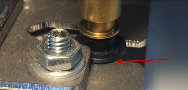
Then, take the nozzle up so that the nozzle collar raises just a bit from the holder bottom plate. Be careful, raising too much would try to pull off the nozzle. Note the small gap:
Take the nozzle down a mm or two (shift+F12), so that the nozzle rests gently on the bottom plate. Click “Get coordinates”.
Alt+F6 moves 10mm to right. Pressing this twice takes the nozzle fully out of the holder:
Click “Get coordinates”.
Finally, click “Goto Z0” button at top right. Click “Get coordinates” once more.
You have now set the moves needed to load the first nozzle.
Nozzle 1 unload moves
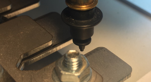
The Y coordinate hasn’t changed during the load sequence, so don’t change it when you move the nozzle to unload start position. A good place to start is to have the nozzle over the slot, but not yet touching anything. Move the nozzle with X and Z keys so, that it looks about like this:
Click the number 1 in the nozzle column of the “Unload:” table to set focus to right spot, then click “Get coordinates” on the “Unload:” table top right:
Lower the nozzle on the lower plate so, that it gently touches:

Click “Get coordinates”.
Move the nozzle to left so that it gets close but not touches the end of the slot:

Note the cap between the nozzle and the bottom of the slot. Click “Get coordinates”.
Take the nozzle up somewhat (like 10mm, alt+F11) and note, how the magnet pulls the nozzle in position. Click “Get coordinates”.
Finally, click “Goto Z0” and “Get coordinates” to finish the unload sequence setup.
NOTE: Before you do any testing on the automatic operations, make sure that the status information on the bottom section matches to the real situation. You don’t want to damage a nozzle by trying to load another nozzle on an occupied adapter, for example.
For first moves, use low speeds, such as 500 on all axis. Test the functioning: Put 1 in the box by the “Change” button and click “Change”:

The program executes the load moves. Put 0 and click “Change”, and the nozzle is unloaded. If you are not happy, tune the sequence; you now know how.
Here is a video showing the sequences loading and unloading nozzle 1 in my system. For reference, the speeds in the video are 500 for illustration; in real life I use 2000 for X and Y and 1000 for Z. Also, first moves are full speed: On video, full Z speed is 6000.
Rest of the nozzles
Your nozzle adapter is now empty and the program status (above the big “Home” button) should show “–” to indicate no nozzle loaded. (The “Force status” button in the above picture doesn’t perform any moves, it only sets the status to the nozzle number in the box. 0 means no nozzle in the adapter.) Right click the first nozzle and select “Goto to start position”. The distance form nozzle to nozzle in the holder is 22mm. If you put 22 to the Y box at the bottom section, select relative move and click Y, you’ll get a good start position for the next nozzle. However, that is not reliable; you would be very lucky to have the nozzle holder exactly parallel to the Y axis. For the same reason, the function “Copy moves from nozzle 1” only gives you a good starting point for the move sequences for other nozzles. Don’t use them without checking.
Final testing
Once you are happy with all the moves, click “Save values” and check “Nozzle change Enable”. then you can find comfortable speeds instead of the slow speeds used in setup. Speed is not very important here; in practice there are not that many nozzle changes in a placement job for speed to make a difference. (Ok, swift operation of a machine you built yourself is cool:-). ) For reference, my speeds are full speed for start and finish moves, 2000 for X,Y and 1000 for Z.
Next (Nozzles runout calibration)