Select Up camera to view and check “Draw cross” for it. First, focus the camera. The “reference” surface of the system is PCB top surface, when the PCB is put on your work table. So, use a blank PCB to raise another PCB from your table, and set the focus.
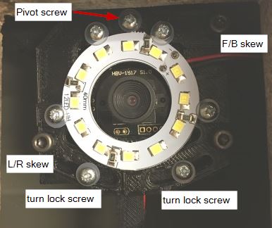
Alignment screws
Here is an image of the alignment screw on the up cam module:
Align the Camera, Set the Image Size
Place a ruler above the camera so, that its edge aligns to the middle of the image. Select the down looking camera and align the ruler with the cross (machine X axis). With the help of this ruler, adjust the alignment of the up-looking camera. Again, tighten the turn lock screws first, and the pivot screw last.
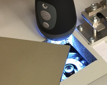
Like you did with the down camera, use a mirror to adjust the skew of the up looking camera. Use a 4mm hex key to adjust the L/R (left/right) and F/B (front/back) skew bolts. This might be awkward, sorry about this. For inspiration, this is how I did it on my machine:
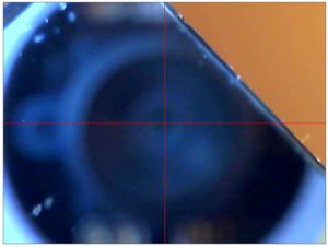
I used a corner of a mirror to get access to the adjustment screws. I turned the power off so that the light reflection from the mirror did not blind the camera. Finally, in my low lit basement lab, I used a flashlight to get some light in the hole. This is what I saw:
Blurry and somewhat difficult to adjust, but gets the job done.
Previous (Downlooking Camera Setup)
Next (Vision Processing Setup)


