(For kits delivered before June 2021, see this page: Downlooking Camera Setup )
Select downlooking camera to the display window.
Set focus and camera height
The cameras have a manual focus ring.The down looking camera height adjustment uses a set of three mounting holes at different heights. When finding the height you want to use, using the lowest screw only is sufficient; add the two other when you have decided the height.
The 4k cameras are easier to focus when “Show pixels” is on. Use this setting when focusing. Untick the “Show pixels” when you are setting the camera field of vision.
Set the camera height so, that the largest component you will be using fits in the image with “Show pixels” off, with some room to spare. Focus to the surface level of a PCB.
Once you have set the focus, re-attach the light diffuser, if you removed it when installing.
Align the Camera
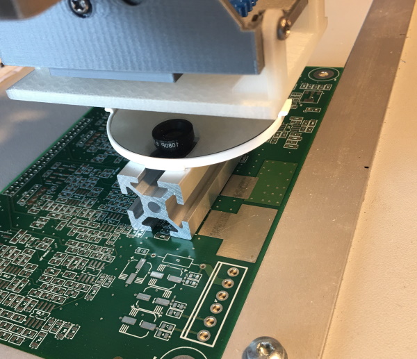
The goal is to make the camera look directly down. First, put a mirror on the table under the camera, so that you see the camera module reflection on the image box. It will be out of focus. At the time of writing, the 4k cameras are rather new. I think you can retune the focus for the alignment, but I’m not sure. You could refocus it for tuning, or put something level under the mirror to make the focusing distance shorter. I used a piece of aluminium extrusion:
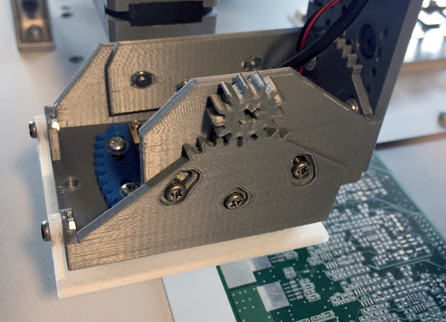
Using the supplied adjustment tool gear on the side of the camera, adjust the front-back camera alignment so that the center of the lens image as reflected on the mirror, gets to the cross line:
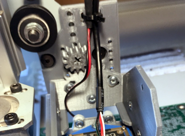
Similarly, for left-right alignment, use the tool on the back plate:
Once done, the center of the lens reflection from the mirror should be at the center of the cross drawn on the image box. Lock the alignment by tightening the screws. Start the tightening from the screws in the slots in order to avoid fouling the trim. Note, that the back-front trim will be locked on both sides of the mount.
Finally, we need to trim the rotation. Put a ruler on your table, and adjust its position or jog the machine so that a point on the edge of the ruler aligns with the center of the cross. (Hint: At this point, you might put a needle to your table and support that point of the ruler against it.) Move the machine in left-right direction to the other end of the ruler. Adjust the ruler so, that at both ends, the ruler edge aligns with the center of the cross. Your ruler now aligns exactly to the machine X axis. Adjust the camera rotation so, that the horizontal red line is parallel to the ruler edge:

Tighten the screws and double check the alignment and focusing.
Set the Camera Units
Select “Show pixels”. Check the “Draw Box” tick box and adjust zoom to less than 2 or turn it off, so that the box fits in the image. Put a ruler under the camera or use a caliber to measure the box size, like this:
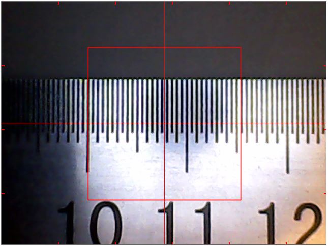
Put the true size of the box (here I put in 15.4mm) to “Box X” and “Box Y”. (There shouldn’t be a big difference in X and Y, if any.) Your machine now knows the size of things it is looking at. (Please note that the image is from earlier low res cameras; your box size will be much smaller.)
NOTE: This method is to get you started. When we get to the measurements using camera, you can measure an object of known size (such as a washer or something similar) and get results in pixels. This will allow you to input the pixels/mms ratio more accurately.
NOTE: If you change camera resolution, re-check the pixel size.