Select Up camera to view and check “Draw cross” for it. First, focus the camera. The “reference” surface of the system is PCB top surface, when the PCB is put on your work table. So, use a blank PCB to raise another PCB from your table, and set the focus.
Alignment screws
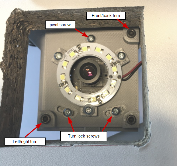
Here is an image of the alignment screws on the up cam module:
Align the Camera, Set the Image Size
Place a ruler above the camera so, that its edge aligns to the middle of the image. Select the down looking camera and align the ruler with the cross (machine X axis). With the help of this ruler, adjust the alignment of the up-looking camera. Again, tighten the turn lock screws first, and the pivot screw last.
Finally, measure and set the box size as you did with the down looking camera.
Previous (Downlooking camera setup)
Next (Vision Processing Setup)