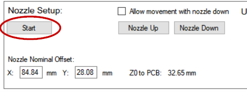
The system needs to know the distance of the nozzle tip in down position relative to the down looking camera image center. The distance is called “nozzle nominal offset”, and you set this up at the Nozzle Setup section on the Setup Video Processing page.
First, make sure that the A axis is at zero orientation. Attach a nozzle to the nozzle adapter and click “Start” on the Nozzle Setup:
The system asks you to jog the nozzle at a point on a PCB. The easiest way* I’ve found so far to do this is to take a post-it note, cut a piece of from the corner (use the glue section to hold the paper in place) and attach it to a blank piece of PCB. Jog nozzle down on the PCB so that it just touches but the PCB is easy to move, and push the corner to the outside of the nozzle, like this:

(*: See end of this page for alternative methods)
Click “Next”. The system asks you to jog the camera over the same spot. Move the camera at the paper corner. Then put nozzle radius on the move boxes X and Y, and select relative. I used #3 nozzle; it has outside diameter of 2.2 mm, so I needed 1.1mm:

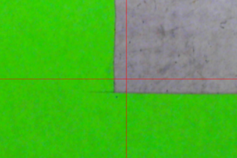
Click “Go:”, and the camera moves to the spot, where the nozzle center was:
The nozzles outside diameters are 1.0, 1.5, 2.2, 4.0, 6.2 and 9.0 mm.
Click “Next” on the Nozzle Setup. The view changes to up camera, and the software asks you to jog the nozzle over the up looking camera. Do that, and once you are close, click “Nozzle Down” and check “Allow movement with nozzle down”. Jog the nozzle tip exactly over the camera and click “Set” on the” Up Camera” location setup:

This process established the up camera location and nominal value for nozzle offset (nozzle tip to down looking camera at PCB level). The true nozzle offset is the nominal offset with the calibration value added; later, we’ll see if nozzle runout (wobble during rotation) correction is needed and find the calibration values.
Click “Nozzle Up” and uncheck “Allow movement with nozzle down”.
*: Alternatively, you can use carbon paper, masking tape, soft pencil blackened paper or other materials that leave a mark where the nozzle pressed down.
Also, you can get pretty good results by using a calibration help figure:
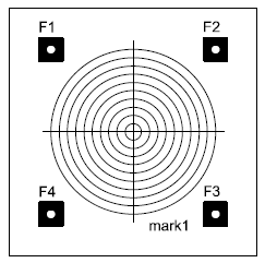
Using the circles it is possible to get below 0.1mm accuracy by eye. Do not jog the machine in X or Y direction while the nozzle is touching the PCB. Instead, note the adjustment you need to do, take needle up a bit, move the machine and take the needle down until it goes exactly where you want it.
You can tune the offset manually as well. Click “Probe (n.c.)” on low right corner on the user interface. This will take the nozzle down to a target shown on the down looking camera, not using nozzle runout (wobble) correction. (The n.c. means no correction). If the nozzle is not landing exactly on the target, you can change the nominal offset, until you are happy.