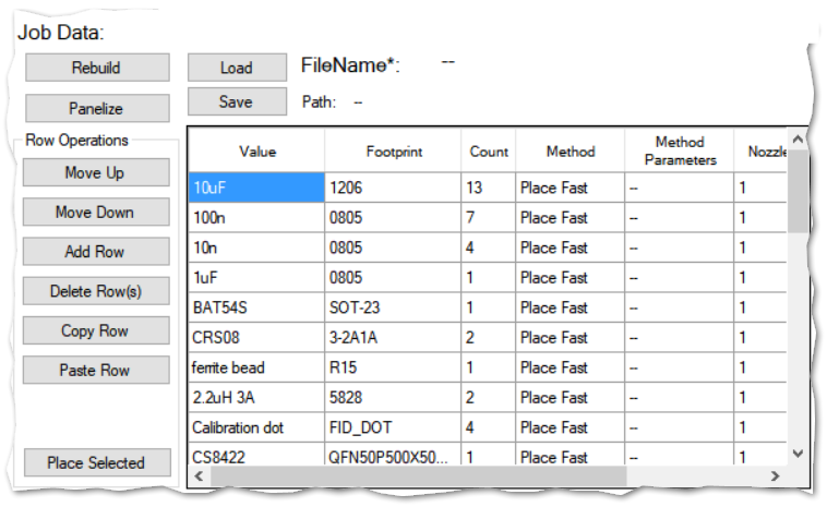
Thw Job Data table is where you tell the software what you want to do to each type of component. Even when you place a single component (triggered at CAD data, component operations section), the process needs the information at Job Data to be set correctly. Here is the image of Job data table again:

The columns of the table are:
“Value“: The value of a part, such as 10uF for a capacitor and 10k for a resistor.
“Footprint“: The package of the part, such as 0805 for passives, SOIC-8 for a small IC and so on. Value and footprint together define a component type. The Job Data table build process (triggered by loading a CAD data if job data file doesn’t yet exist, or the “Rebuild” button.
“Count“: As implied, how many of these type of components your data has.
“Method“: How to handle these type of parts. You can also have operations during a job that don’t need parts information, such as pause or recalibrate. For details of available methods, see here.
“Method parameters“: Additional info, that a method might need. For example, a placement method also needs to know where to pick up this type of component.
“Nozzle“: The nozzle used to handle this type of component. Note: For more complex jobs, you can click the header to arrange the table rows by nozzle; this minimizes nozzle changes for a job, saving some time.
Beta: “Placement method”: Either none (default) or Up Cam Assisted.
Beta: “Placement algorithm”: If Up Cam Assisted method is used on placement, the component is taken over the up looking camera, the selected vision algorithm is used to measure the component position on the nozzle and the measured correction is used on the placement. Please see this page.
“Components“: The list of component designators that are handled by this row. For example, R1, R2, R3 etc. This column is not visible unless you scroll the table.