The nozzles should run very true, with little or no runout ( wobble). The software does give you the possibility to calibrate and correct for the runout. Do your own experiments and performance analysis. If you find that you don’t need runout correction, you can check the “Don’t use nozzle correction” on the run job page. I fyou do want to use nozzle runout correction, this page will tell you how to do this.
The nozzle change functions should be operational and smooth at this point.
The repeatability of the nozzles is excellent; in other words, if you load a nozzle, unload it and use another one and then load the first one again, the first nozzle will sit on the adapter on same location each time, with high accuracy. Therefore, the software stores the calibration and re-uses the results. Therefore, you only need to succeed on the calibration once per nozzle.
There are several ways to do the nozzle calibration. The easiest is to set Vision Algorithm column on “Vision Parameters:” table to “Nozzle tip” for all nozzles and leave “Override Size” unchecked. This allows you to run the calibrations on the “Setup Video Processing” page.
Goto Setup Video Processing page. Select Up looking camera to view. Click “Special Options” at the up right corner. This subpage opens:

Select 1 on the number box and click change. The system changes to nozzle #1.
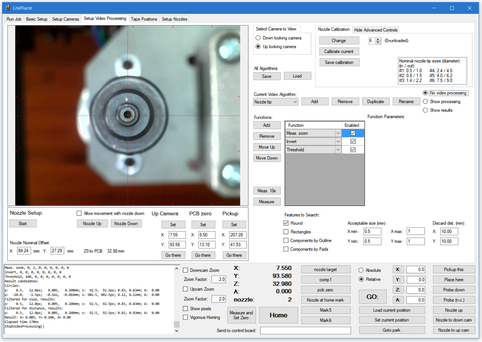
Click “Go there” under Up Camera and click “Nozzle Down”. You now have nozzle #1 at the up camera location, and you see something like this:
For this nozzle, it is easiest to target the inside hole. I used zoom, invert and threshold functions to get this:

The green highlight shows that the vision algorithm sees the inner hole that we want, as well as the collar. by limiting the acceptable size, only the inside hole will be considered. Click “Calibrate current” in the box at up right. The system runs the calibration routine: It measures the hole position at several rotation values and stores the results internally.
Repeat with other nozzles. Change the parameters and the acceptable size as needed. Remember, that you only need to get the calibration to pass once per nozzle.
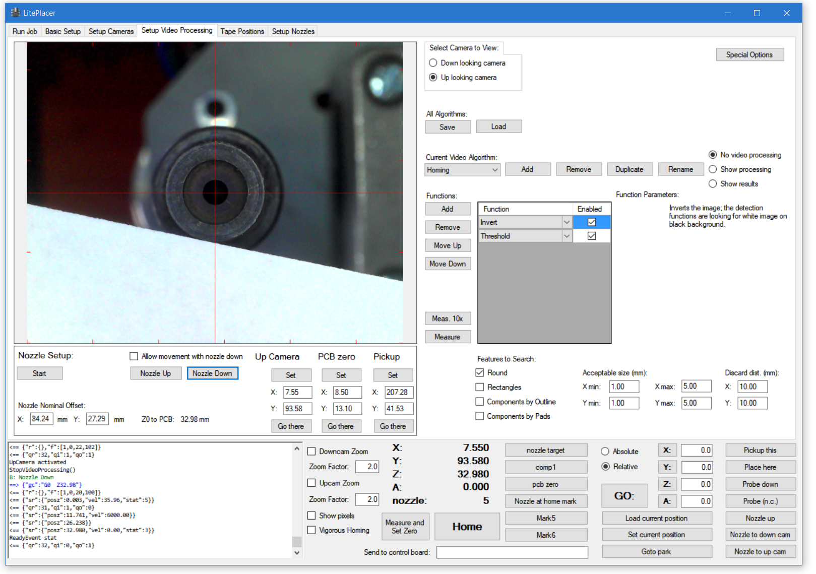
Here is my view with nozzle #5 loaded:

There are several round features; I used a piece of paper to make sure which is the outer edge of the nozzle:
Then, invert and tuning the threshold value gave me reliable recognition of the inner side of the nozzle. Even thought the contrast isn’t the greatest, the constant illumination makes it good enough:
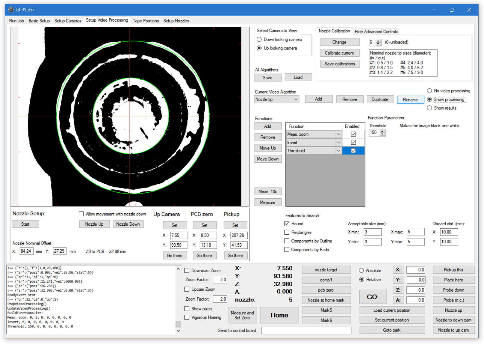
Finally, looking at the results ensures that the right feature is looked at. Note that the log says after filtered for distance, that the one remaining result has 3.97mm size. Note also, that the nozzles inside and outside diameters are listed in the Nozzle Calibration window. Nozzle #4 inside diameter is 4.0mm, and I have set acceptable size to be between 3 and 5mm to get an unique result:

Congratulations! You have now finished the build and and calibration of the LitePlacer machine!
It is a good idea to go trough your work, check the functionality and re-tune things that might need it. after that, you need to set up some tapes and you are ready to run the first job.
Previous (Automatic Nozzle Change Setup)
Next (Checking the calibration)