Tape Measures and Orientations
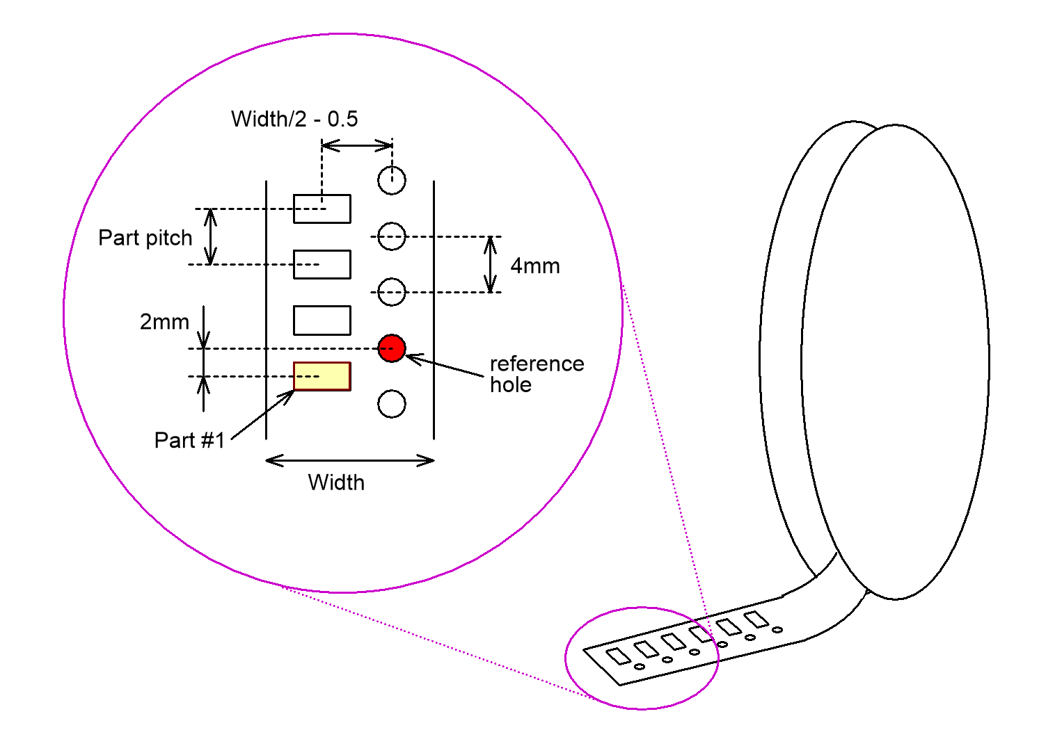
SMD parts come mounted on a tape, and if you buy many of them, the tape comes on a reel. There are some standards on this. The holes are 1.5mm in diameter and are 4mm apart. There is a hole 2mm from a part center. The tape width is a multiple of 4mm, as is the part pitch, except for 0402 and smaller parts, where the part pitch is 2mm. The part center distance from the holes is width / 2 – 0.5mm. The parts are placed on a tape so, that there is a hole 2mm from a part center. This is our reference hole:
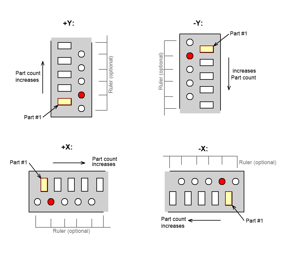
It is up to you to decide which way to put the tape strips on the table. The orientation is the direction where part count increases. The orientations are:
Place Rulers
It is helpful to have rulers with part count helping the tape strip placement. On the Downloads page you’ll find some that I have used. Print these on adhesive label and cut some out. Using the camera as alignment help, place the rulers square to X or Y axis. If you down use the rulers, draw alignment marks, square to the axis. Attach double-size tape at the tape side of the guides.
The camera uses tape holes to find the parts. Depending on your tabletop color, you might need to extend the ruler to reach under the tape holes. On a very white table and white paper tape, you might need to have some darker or black color where the tapes holes go. the goal is to have reasonably contrast on the holes, so the camera can find them reliably.
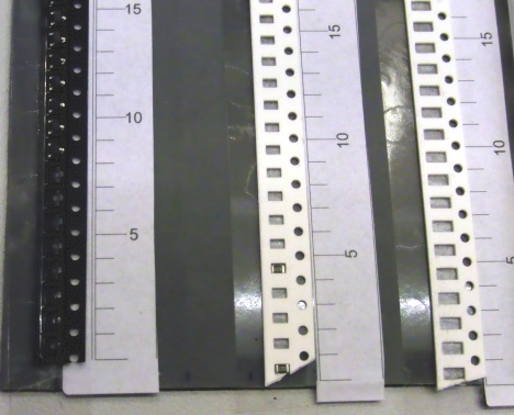
Place some tapes at the rulers.
Setup Tape Positions
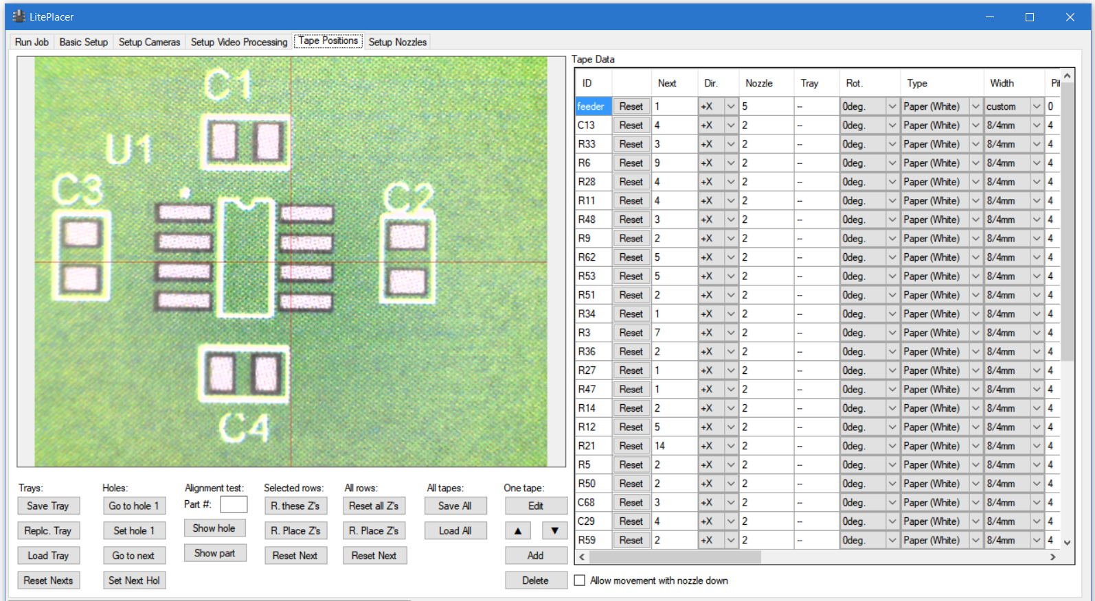
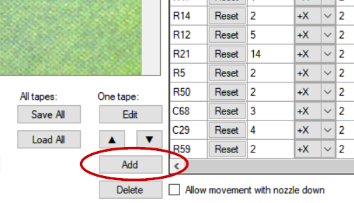
You tell the machine the location of the tapes on the “Tape Positions” page. There you’ll find a table of tape data and lots of buttons, although your table will be empty at start:
Jog the machine so, that the camera image is at a reference hole of a tape. You don’t need to be very accurate on this, the exact location is measured by the camera at run time. Somewhere inside the hole is good enough.
The “Add” button at “One tape:” column adds the position to the table:
This opens the tape data editing dialog:
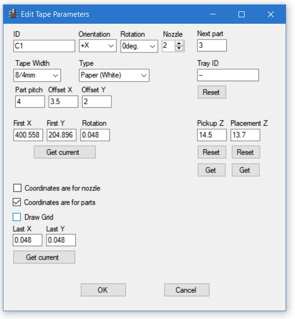
For regular tapes, only the few top items are needed:
- The “ID” column is the name for this tape; you can use any name you want: the component values of the tape, the label or number (if you wrote any) or whatever. The important thing is to use a name that you can identify later.
- “Orientation” is the orientation shown above. This tells the machine which direction to look for next parts.
- “Part Rotation” tells which way the components are placed in the tape pockets. Unfortunately, there is no industry standard. for this. Let’s consider a part that has CAD rotation as 0; that is, you didn’t rotate the part at all during PCB design, and the CAD data has 0 as the rotation value. Rotation value 0 in tape parameters means that components from a tape placed on the table in +Y orientation, with CAD data rotation also 0, will be placed to the PCB “as is”. If rotation parameter is 90 degrees, this part is placed on the PCB rotated 90 degrees counterclockwise (positive direction). The CAD data rotation is also added to the actual part rotation used in placement. When setting up a tape, think part rotation related to +Y oriented tape. The rotation changes resulting from other tape orientations are automatically taken to account.
- “Nozzle” is the preferred nozzle number to use for this part.
- “Next part” column tells which part # will be taken next.
- “Tape Width” dropdown column has the standard tape width and component pitch selections. The first number is the tape width, the second number is component pitch. Selecting a standard width automatically updates the pitch and offset values correctly in he dialog.
- “Type” dropdown box contains the vision algorithms you have defined.
Set these for each tape you put on your table. For explanation of the rest of the items in the dialog, please see this page on the software reference section.
The most important sections on this page are:
One Tape:
The “Edit” button re-opens the edit dialog above. Select a cell in the table and click edit and thhe opens. The arrows arrange the table. As noted: To add another tape, jog the machine to the first reference hole of a tape and click “Add” and fill the edit tape dialog. Also, you can open the dialog by right clicking a cell in the table. To delete a tape definition, select a cell on the table and click “Delete”.
Alignment test:
Here you can test that you have set the tape correctly. Select a cell in the table for the tape you are testing. Then:
“Part #”: Put a part number in this box.
“Show hole” takes the camera above the hole that will be used to find this part.
“Show part” takes the camera above the part itself. A blue arrow shows the orientation of the part.
Holes:
Select a cell in the table on a tape row:
“Go to hole 1” takes the machine over the first hole.
“Set hole 1”: Sets the current machine position as the location of the first hole of the tape.
“Go to next” takes the machine over the hole that will be used to locate the part, that will be used next.
“Set Next Hole”: Sets the current machine position as the location of the next hole of the tape.
For the full description of the items in this page, please see this page on the software reference section.
Previous (Checking the calibration)