Before using the machine for real, let’s do a simple “Hello World!” job. The files for this example are in this zip archive.
Prepare for the job
First, we need to put some parts on the table. If you haven’t yet done so, place some 0603 and 0805 passives on tapes as described on the “Tapes setup” page.
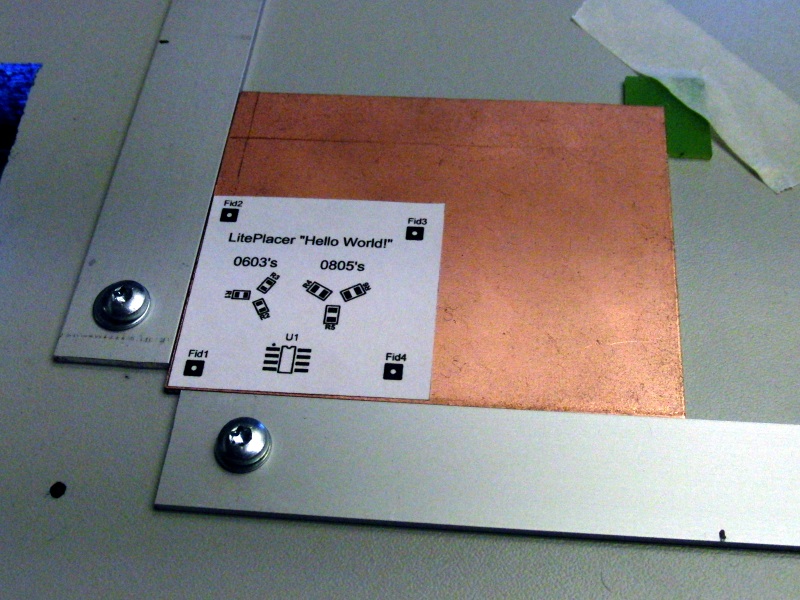
We don’t need to manufacture a real PCB for this test, a mockup is just fine. Print the Hello World PCB image PDF, making sure your printer does not do too much scaling on the image; the nominal size is 42.5mm x 41mm. Cut out the image and attach it to a blank PCB piece. A spray-on post-it glue is great for this, available at you local office supplies store. Put some on your printout as well to simulate the soldering paste stickiness. Put the board mockup to your PCB jig and secure the placement. An L shaped piece of circuit board and some masking tape is sufficient for this purpose:
I assume that you have already done all the calibrations.
Load data
Select the “Run Job” tab. Click the “Load” button at the “CAD Data” section on top of the page and select the file “hello world pick and place.csv”. The pick and place data is read in and the Job Data table is filled with a summary. The fiducials are named as Fid1..Fid4, so the system automatically recognizes them. Please see the Input File Format page for the requirement of the pick and place file. The result is like this:
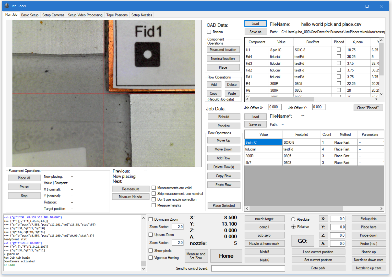
The top table is the CAD data table, where each component is listed individually. The bottom table is the Job data table, where the components are grouped together.
Check locations, measure the board
Click any cell on the Fid4″ row on the CAD Data table and click the “Nominal Location” button:
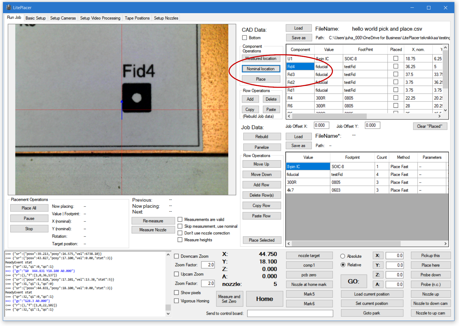
The machine moves so, that the Fid4 is located close to the center of the image. This doesn’t need to be accurate, only close enough that the fiducial vision algorithm finds the target and that the correct fiducial mark is the closest result. Mine above is actually rather bad, but it still works fine.
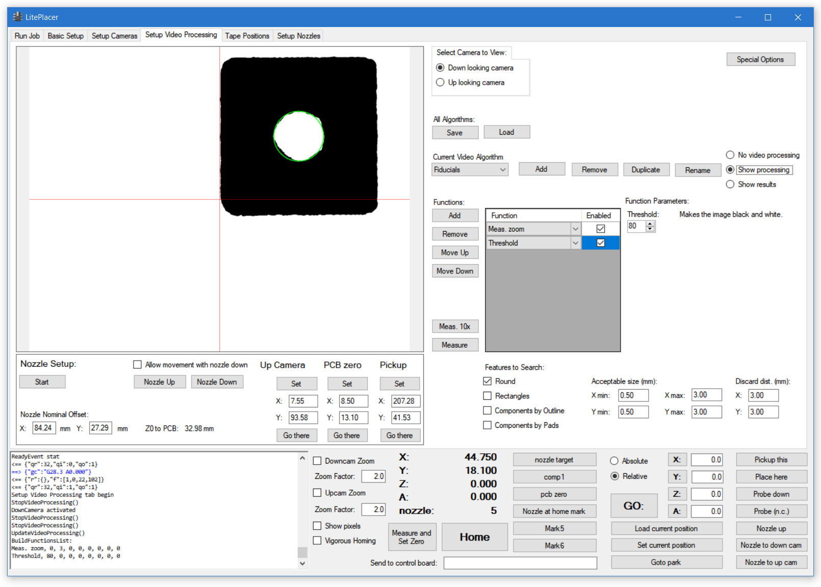
Go to the “Setup Video Processing” page, select “Fiducials” from the “Current Video Algorithm” drop-down box and trim the algorithm so, that you get a good recognition. Zoom and threshold should be all that you need:
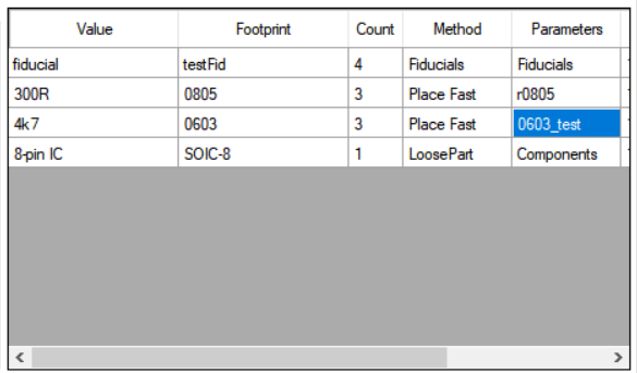
Go back to the Run job page. Look at the Job data table. On each component group, you have these columns:
-Value, Footprint: These come from your CAD system. The components go to the same group if both of these are identical.
-Count
-Method: This tells how the group should be handled. Available methods are listed in the software reference section here.
-Parameters: Additional info for the method, such as vision algorithm or tape name
(Scroll to see these:)
-Nozzle: If the method involves placing, the nozzle that is used. Note: For more complex jobs, you can click the header to arrange the table rows by nozzle; this minimizes nozzle changes for a job, saving some time.
-Components: List of components belonging to the group.
Notice, that the fiducials are automatically recognized* and “Fiducials” is placed on the method box. Click the “Parameters” cell on the Fiducials row. You are presented with a small dialog with a drop-down box containing all the vision algorithms you have defined. Select Fiducials.
*If you name your fiducials as FI1, FI2, … or FID1, FID2, … the program does that (case insensitive); otherwise you need to indicate them by setting the method as “Fiducials”.
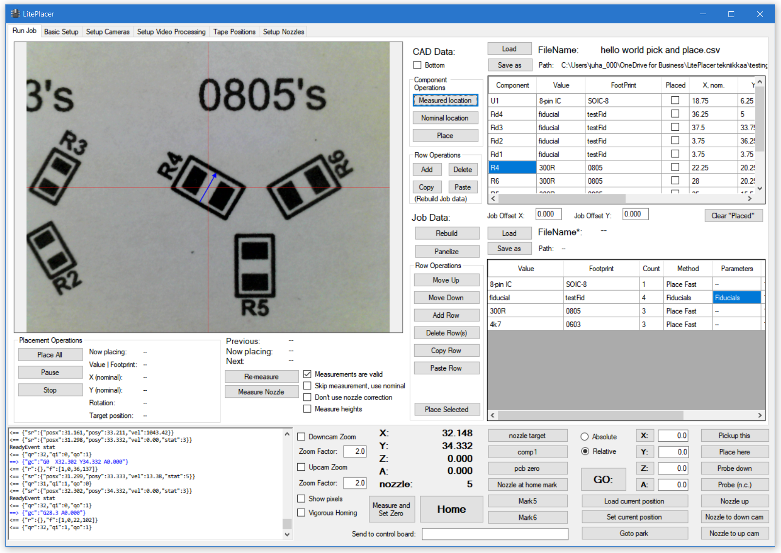
Click any component on the CAD data table (R4 in the example). Click “Measured location” button. The software tells you that the component locations are not measured yet and asks “Measure now?”. Answer yes. The software goes through all the fiducials, measures their locations in machine coordinates, calculates the transform between machine and CAD coordinates and calculates the locations of each component. Finally, the software moves the machine to the location of the component and shows it at the center of the camera view, with a small arrow showing the part orientation:
We are going to place the resistors from the tape strips and the IC as a loose part. The software uses “place fast” as the default method. Change it to “Loose part pickup” for the IC and select “Components” for the method. Select also a nozzle for it, that is suitable for SOIC8 IC (#4).
Place an SOIC8 ic on your loose part pickup spot. Using instructions and examples on this page, tune your “Components” algorithm so, that it finds the part reliably.
Using the “Move Down” button, move this row to the bottom.
For the resistors, put down some tapes as described on the “Tapes Setup” page. Most likely, These are on white paper tape. On the video processing setup, tune the “paper tape” algorithm so, that you get a good recognition of the holes. Test this using the “Alignment test” section. Note, that the vision algorithm used on a tape is associated with the tape. The default algorithms and their names is just a suggestion and a starting point. You might find it necessary to use specific algorithms for some specific tapes.
Click the parameters cell for both 300R/0805 and 4k7/0603 parts. A window pops up; click “Select” on the tapes that have the corresponding parts. Select a suitable nozzle for these passives (#2). The job is now ready for placement, and your Job data table looks something like this:
To save a job, click “Save” button above the table. LitePlacer job data files are of type .lpj (LitePlacer Job). If a file with the same name but with .lpj extension is found at the same directory as the pick and place file, it is automatically loaded when the pick and place file is loaded. Of course, you can load a job file manually with the “Load” button.
You are ready to place the parts. You could place the parts row by row (“Place Selected” button). But do click “Place All” in the Placement Operations” box on the left. If the program doesn’t have fresh measurement data in the memory (“Measurements are valid” checkbox), it does the measurement routine again. Then it places the parts, changing nozzles as needed. When it gets to the IC, it ask you to place the part at the loose part position. (You likely have one there already, since you just tuned the algorithm to fit.) Once done, the machine goes to the Park location and you get a message.
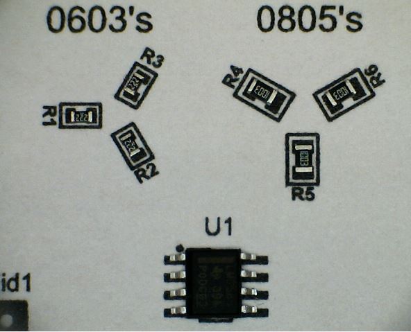
Your results should be something like this:
Congratulations! You have now built your own pick and place machine and have run the first job with it. Your machine is now ready to use. You might still want to prepare some more mockups and familiarize yourself to the operation and capabilities of your machine.